CY7C64013
CY7C64113
modifying the interrupt bits while the Port Config bits are set to “10” is shown in Table 9-1. The events that generate HAPI interrupts
are described in Section 14.0.
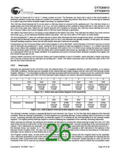
16.8
I2C Interrupt
The I2C interrupt occurs after various events on the I2C compatible bus to signal the need for firmware interaction. This generally
involves reading the I2C Status and Control Register (Figure 13-2) to determine the cause of the interrupt, loading/reading the
I2C Data Register as appropriate, and finally writing the Status and Control Register to initiate the subsequent transaction. The
interrupt indicates that status bits are stable and it is safe to read and write the I2C registers. Refer to Section 13.0 for details on
the I2C registers.
When enabled, the I2C compatible state machines generate interrupts on completion of the following conditions. The referenced
bits are in the I2C Status and Control Register.
1. In slave receive mode, after the slave receives a byte of data. The Addr bit is set if this is the first byte since a start or restart
signal was sent by the external master. Firmware must read or write the data register as necessary, then set the ACK, Xmit
Mode, and Continue bits appropriately for the next byte.
2. In slave receive mode, after a stop bit is detected. The Received Stop bit is set. If the stop bit follows a slave receive transaction
where the ACK bit was cleared to 0, no stop bit detection occurs.
3. In slave transmit mode, after the slave transmits a byte of data. The ACK bit indicates if the master that requested the byte
acknowledged the byte. If more bytes are to be sent, firmware writes the next byte into the Data Register and then sets the
Xmit Mode and Continue bits as required.
4. In master transmit mode, after the master sends a byte of data. Firmware should load the Data Register if necessary, and set
the Xmit Mode, MSTR Mode, and Continue/Busy bits appropriately. Clearing the MSTR Mode bit issues a stop signal to the
I2C compatible bus and return to the idle state.
5. In master receive mode, after the master receives a byte of data. Firmware should read the data and set the Ack and
Continue/Busy bits appropriately for the next byte. Clearing the Master bit at the same time causes the master state machine
to issue a stop signal to the I2C compatible bus and leave the I2C compatible hardware in the idle state.
6. When the master loses arbitration. This condition clears the Master bit and sets the Arbitration Lost bit immediately and then
waits for a stop signal on the I2C compatible bus to generate the interrupt.
The Continue/Busy bit is cleared by hardware prior to interrupt conditions 1 to 4. Once the Data Register has been read or written,
firmware should configure the other control bits and set the Continue bit for subsequent transactions.
Following an interrupt from master mode, firmware should perform only one write to the Status and Control Register that sets the
Continue bit, without checking the value of the Busy bit. The Busy bit may otherwise be active and I2C register contents may be
changed by the hardware during the transaction, until the I2C interrupt occurs.
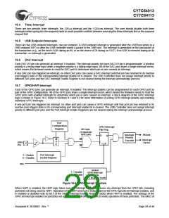
17.0
USB Overview
The USB hardware consists of the logic for a full-speed USB Port. The full-speed serial interface engine (SIE) interfaces the
microcontroller to the USB bus. An external series resistor (Rext) must be placed in series with the D+ and D– lines, as close to
the corresponding pins as possible, to meet the USB driver requirements of the USB specifications.
17.1
USB Serial Interface Engine (SIE)
The SIE allows the CY7C64x13 microcontroller to communicate with the USB host. The SIE simplifies the interface between the
microcontroller and USB by incorporating hardware that handles the following USB bus activity independently of the microcon-
troller:
• Bit stuffing/unstuffing
• Checksum generation/checking
• ACK/NAK/STALL
• Token type identification
• Address checking
Firmware is required to handle the following USB interface tasks:
• Coordinate enumeration by responding to SETUP packets
• Fill and empty the FIFOs
• Suspend/Resume coordination
• Verify and select DATA toggle values
Document #: 38-08001 Rev. **
Page 30 of 48

 CYPRESS [ CYPRESS ]