CY7C64013
CY7C64113
Whenever the count updates from a SETUP or OUT transaction on endpoint 0, the counter register locks and cannot be written
by the CPU. Reading the register unlocks it. This prevents firmware from overwriting a status update on incoming SETUP or OUT
transactions before firmware has a chance to read the data. Only endpoint 0 counter register is locked when updated. The locking
mechanism does not apply to the count registers of other endpoints.
18.6
Endpoint Mode/Count Registers Update and Locking Mechanism
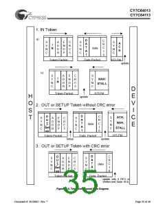
The contents of the endpoint mode and counter registers are updated, based on the packet flow diagram in Figure 18-5. Two
time points, UPDATE and SETUP, are shown in the same figure. The following activities occur at each time point:
UPDATE:
1. Endpoint Mode Register - All the bits are updated (except the SETUP bit of the endpoint 0 mode register).
2. Counter Registers - All bits are updated.
3. Interrupt - If an interrupt is to be generated as a result of the transaction, the interrupt flag for the corresponding endpoint is
set at this time. For details on what conditions are required to generate an endpoint interrupt, refer to Table 19-2.
4. The contents of the updated endpoint 0 mode and counter registers are locked, except the SETUP bit of the endpoint 0 mode
register which was locked earlier.
SETUP:
The SETUP bit of the endpoint 0 mode register is forced HIGH at this time. This bit is forced HIGH by the SIE until the end of the
data phase of a control write transfer. The SETUP bit can not be cleared by firmware during this time.
The affected mode and counter registers of endpoint 0 are locked from any CPU writes once they are updated. These registers
can be unlocked by a CPU read, only if the read operation occurs after the UPDATE. The firmware needs to perform a register
read as a part of the endpoint ISR processing to unlock the effected registers. The locking mechanism on mode and counter
registers ensures that the firmware recognizes the changes that the SIE might have made since the previous IO read of that
register.
Document #: 38-08001 Rev. **
Page 34 of 48

 CYPRESS [ CYPRESS ]