CY7C64013
CY7C64113
17.2
USB Enumeration
The USB device is enumerated under firmware control. The following is a brief summary of the typical enumeration process of
the CY7C64x13 by the USB host. For a detailed description of the enumeration process, refer to the USB specification.
In this description, ‘Firmware’ refers to embedded firmware in the CY7C64x13 controller.
1. The host computer sends a SETUP packet followed by a DATA packet to USB address 0 requesting the Device descriptor.
2. Firmware decodes the request and retrieves its Device descriptor from the program memory tables.
3. The host computer performs a control read sequence and Firmware responds by sending the Device descriptor over the USB
bus, via the on-chip FIFOs.
4. After receiving the descriptor, the host sends a SETUP packet followed by a DATA packet to address 0 assigning a new USB
address to the device.
5. Firmware stores the new address in its USB Device Address Register after the no-data control sequence completes.
6. The host sends a request for the Device descriptor using the new USB address.
7. Firmware decodes the request and retrieves the Device descriptor from program memory tables.
8. The host performs a control read sequence and Firmware responds by sending its Device descriptor over the USB bus.
9. The host generates control reads from the device to request the Configuration and Report descriptors.
10.Once the device receives a Set Configuration request, its functions may now be used.
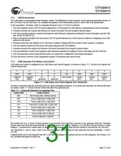
17.3
USB Upstream Port Status and Control
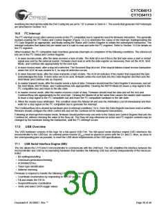
USB status and control is regulated by the USB Status and Control Register, as shown in Figure 17-1. All bits in the register are
cleared during reset.
7
6
5
4
3
2
1
0
R/W
R/W
R
R
R/C
R/W
R/W
R/W
Endpoint
Size
Endpoint
Mode
D+
Upstream
D–
Upstream
Bus Activity
Control
Bit 2
Control
Bit 1
Control
Bit 0
Figure 17-1. USB Status and Control Register 0x1F (read/write)
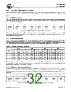
The three control bits allow the upstream port to be driven manually by firmware. For normal USB operation, all of these bits must
be cleared. Table 17-1 shows how the control bits affect the upstream port.
Table 17-1. Control Bit Definition for Upstream Port
Control Bits
Control Action
000
Not Forcing (SIE Controls Driver)
Force D+[0] HIGH, D–[0] LOW
Force D+[0] LOW, D–[0] HIGH
Force SE0; D+[0] LOW, D–[0] LOW
Force D+[0] LOW, D–[0] LOW
Force D+[0] HiZ, D–[0] LOW
Force D+[0] LOW, D–[0] HiZ
Force D+[0] HiZ, D–[0] HiZ
001
010
011
100
101
110
111
Bus Activity (bit 3) is a “sticky” bit that indicates if any non-idle USB event has occurred on the upstream USB port. Firmware
should check and clear this bit periodically to detect any loss of bus activity. Writing a ‘0’ to the Bus Activity bit clears it, while
writing a ‘1’ preserves the current value. In other words, the firmware can clear the Bus Activity bit, but only the SIE can set it.
The Upstream D– and D+ (bits 4 and 5) are read only. These give the state of each upstream port pin individually: 1=HIGH,
0=LOW.
Endpoint Mode (bit 6) and Endpoint Size (bit 7) are used to configure the number and size of USB endpoints. See Section 18.2
for a detailed description of these bits.
Document #: 38-08001 Rev. **
Page 31 of 48

 CYPRESS [ CYPRESS ]