CY7C64013
CY7C64113
just before the RETI instruction. The program counter CF and ZF are restored and interrupts are enabled when the RETI
instruction is executed.
The DI and EI instructions can be used to disable and enable interrupts, respectively. These instructions affect only the Global
Interrupt Enable bit of the CPU. If desired, EI can be used to re-enable interrupts while inside an ISR, instead of waiting for the
RETI that exists the ISR. While the global interrupt enable bit is cleared, the presence of a pending interrupt can be detected by
examining the IRQ Sense bit (Bit 7 in the Processor Status and Control Register).
16.1
Interrupt Vectors
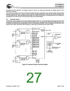
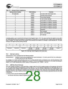
The Interrupt Vectors supported by the USB Controller are listed in Table 16-1. The lowest-numbered interrupt (USB Bus Reset
interrupt) has the highest priority, and the highest-numbered interrupt (I2C interrupt) has the lowest priority. Although Reset is not
an interrupt, the first instruction executed after a reset is at PROM address 0x0000h—which corresponds to the first entry in the
Interrupt Vector Table. Because the JMP instruction is 2 bytes long, the interrupt vectors occupy 2 bytes.
USB Reset Clear
Interrupt
CLR
To CPU
Vector
Q
1
USB Reset IRQ
D
Enable [0]
(Reg 0x20)
128-µs CLR
128-µs IRQ
1-ms CLR
1-ms IRQ
CPU
USB
Reset
Int
CLK
IRQ Sense
IRQ
IRQout
AddA EP0 CLR
AddA EP0 IRQ
AddA EP1 CLR
AddA EP1 IRQ
AddA EP2 CLR
AddA EP2 IRQ
CLR
Q
1
D
Global
Interrupt
Enable
Bit
Int Enable
Sense
Enable [2]
(Reg 0x21)
AddA EP3 CLR
AddA EP3 IRQ
AddA
ENP2
Int
CLK
AddA EP4 CLR
AddA EP4 IRQ
Controlled by DI, EI, and
RETI Instructions
CLR
Interrupt
Acknowledge
DAC CLR
DAC IRQ
GPIO CLR
GPIO IRQ
2
I C CLR
CLR
2
Q
I C IRQ
1
D
Enable [6]
(Reg 0x20)
Interrupt
Priority
Encoder
2
I C
CLK
Int
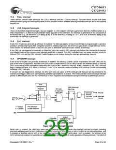
Figure 16-3. Interrupt Controller Functional Diagram
Document #: 38-08001 Rev. **
Page 27 of 48

 CYPRESS [ CYPRESS ]