CY7C64013
CY7C64113
18.0
USB Serial Interface Engine Operation
USB Device Address A includes up to five endpoints: EPA0, EPA1, EPA2, EPA3, and EPA4. Endpoint (EPA0) allows the USB
host to recognize, set-up, and control the device. In particular, EPA0 is used to receive and transmit control (including set-up)
packets.
18.1
USB Device Address
The USB Controller provides one USB Device Address with five endpoints. The USB Device Address Register contents are
cleared during a reset, setting the USB device address to zero and marking this address as disabled. Figure 18-1 shows the
format of the USB Address Registers.
7
6
5
4
3
2
1
0
Device
Address
Enable
Device
Address
Bit 6
Device
Address
Bit 5
Device
Address
Bit 4
Device
Address
Bit 3
Device
Address
Bit 2
Device
Address
Bit 1
Device
Address
Bit 0
Figure 18-1. USB Device Address Register 0x10 (read/write)
Bit 7 (Device Address Enable) in the USB Device Address Register must be set by firmware before the SIE can respond to USB
traffic to this address. The Device Addresses in bits [6:0] are set by firmware during the USB enumeration process to the non-zero
address assigned by the USB host.
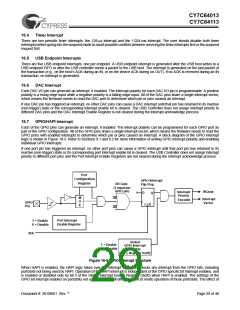
18.2
USB Device Endpoints
The CY7C64x13 controller supports one USB device address and five endpoints for communication with the host. The configu-
ration of these endpoints, and associated FIFOs, is controlled by bits [7,6] of the USB Status and Control Register (0x1F). Bit 7
controls the size of the endpoints and bit 6 controls the number of endpoints. These configuration options are detailed in Table
18-1. The “unused” FIFO areas in the following table can be used by the firmware as additional user RAM space.
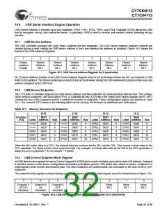
Table 18-1. Memory Allocation for Endpoints
[0,0]
[1,0]
[0,1]
[1,1]
I/Ostatus
[7,6]
Start
Label Address
Start
Start
Start
Size Label Address Size Label Address Size Label Address Size
unused
unused
0xD8
8
8
8
8
8
0xA8
0xB0
0xB8
0xC0
0xE0
8
8
EPA4
EPA3
EPA2
EPA1
EPA0
0xD8
0xE0
0xE8
0xF0
0xF8
8
8
8
8
8
EPA4
EPA3
EPA0
EPA1
EPA2
0xB0
0xA8
0xB8
0xC0
0xE0
8
8
unused
unused
0xE0
EPA2
EPA1
EPA0
0xE8
0xF0
0xF8
EPA0
EPA1
EPA2
8
8
32
32
32
32
When the SIE writes data to a FIFO, the internal data bus is driven by the SIE; not the CPU. This causes a short delay in the
CPU operation. The delay is three clock cycles per byte. For example, an 8-byte data write by the SIE to the FIFO generates a
delay of 2 µs (3 cycles/byte * 83.33 ns/cycle * 8 bytes).
18.3
USB Control Endpoint Mode Register
All USB devices are required to have a Control Endpoint 0 (EPA0) that is used to initialize and control each USB address. Endpoint
0 provides access to the device configuration information and allows generic USB status and control accesses. Endpoint 0 is
bidirectional to both receive and transmit data. The other endpoints are unidirectional, but selectable by the user as IN or OUT
endpoints.
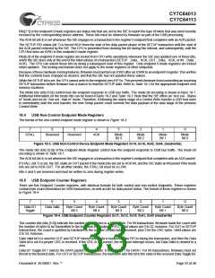
The endpoint mode register is cleared during reset. The endpoint zero EPA0 mode register uses the format shown in Figure 18-2.
7
6
5
4
3
2
1
0
Endpoint 0
SETUP
Endpoint 0
IN
Endpoint 0
OUT
ACK
Mode
Bit 3
Mode
Bit 2
Mode
Bit 1
Mode
Bit 0
Received
Received
Received
Figure 18-2. USB Device Endpoint Zero Mode Register 0x12 (read/write)
Document #: 38-08001 Rev. **
Page 32 of 48

 CYPRESS [ CYPRESS ]