CY7C64013
CY7C64113
Bits[7:5] in the endpoint 0 mode registers are status bits that are set by the SIE to report the type of token that was most recently
received by the corresponding device address. These bits must be cleared by firmware as part of the USB processing.
The ACK bit (bit 4) is set whenever the SIE engages in a transaction to the register’s endpoint that completes with an ACK packet.
The SETUP PID status (bit 7) is forced HIGH from the start of the data packet phase of the SETUP transaction until the start of
the ACK packet returned by the SIE. The CPU is prevented from clearing this bit during this interval, and subsequently, until the
CPU first does an IORD to this endpoint 0 mode register.
Bits[6:0] of the endpoint 0 mode register are locked from CPU write operations whenever the SIE has updated one of these bits,
which the SIE does only at the end of the token phase of a transaction (SETUP... Data... ACK, OUT... Data... ACK, or IN... Data...
ACK). The CPU can unlock these bits by doing a subsequent read of this register. Only endpoint 0 mode registers are locked
when updated. The locking mechanism does not apply to the mode registers of other endpoints.
Because of these hardware locking features, firmware must perform an IORD after an IOWR to an endpoint 0 register. This verifies
that the contents have changed as desired, and that the SIE has not updated these values.
While the SETUP bit is set, the CPU cannot write to the endpoint zero FIFOs. This prevents firmware from overwriting an incoming
SETUP transaction before firmware has a chance to read the SETUP data. Refer to Table 18-1 for the appropriate endpoint zero
memory locations.
The Mode bits (bits [3:0]) control how the endpoint responds to USB bus traffic. The mode bit encoding is shown inTable 19-1.
Additional information on the mode bits can be found inTable 19-2 and Table 19-3. Note that the SIE offers an “Ack out - Status
in” mode and not an “Ack out - Nak in” mode. Therefore, if following the status stage of a Control Write transfer a USB host were
to immediately start the next transfer, the new Setup packet could override the data payload of the data stage of the previous
Control Write.
18.4
USB Non-Control Endpoint Mode Registers
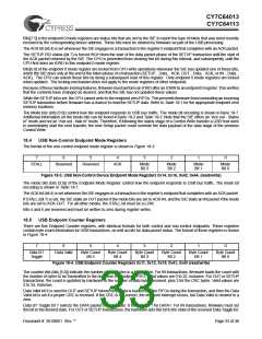
The format of the non-control endpoint mode register is shown in Figure 18-3.
7
6
5
4
3
2
1
0
STALL
Reserved
Reserved
ACK
Mode
Bit 3
Mode
Bit 2
Mode
Bit 1
Mode
Bit 0
Figure 18-3. USB Non-Control Device Endpoint Mode Registers 0x14, 0x16, 0x42, 0x44, (read/write)
The mode bits (bits [3:0]) of the Endpoint Mode Register control how the endpoint responds to USB bus traffic. The mode bit
encoding is shown in Table 19-1.
The ACK bit (bit 4) is set whenever the SIE engages in a transaction to the register’s endpoint that completes with an ACK packet.
If STALL (bit 7) is set, the SIE stalls an OUT packet if the mode bits are set to ACK-IN, and the SIE stalls an IN packet if the mode
bits are set to ACK-OUT. For all other modes, the STALL bit must be a LOW.
Bits 5 and 6 are reserved and must be written to zero during register writes.
18.5
USB Endpoint Counter Registers
There are five Endpoint Counter registers, with identical formats for both control and non-control endpoints. These registers
contain byte count information for USB transactions, as well as bits for data packet status. The format of these registers is shown
in Figure 18-4:
7
6
5
4
3
2
1
0
Data 0/1
Toggle
Data Valid
Byte Count
Bit 5
Byte Count
Bit 4
Byte Count
Bit 3
Byte Count
Bit 2
Byte Count
Bit 1
Byte Count
Bit 0
Figure 18-4. USB Endpoint Counter Registers 0x11, 0x13, 0x15, 0x41, 0x43 (read/write)
The counter bits (bits [5:0]) indicate the number of data bytes in a transaction. For IN transactions, firmware loads the count with
the number of bytes to be transmitted to the host from the endpoint FIFO. Valid values are 0 to 32, inclusive. For OUT or SETUP
transactions, the count is updated by hardware to the number of data bytes received, plus 2 for the CRC bytes. Valid values are
2 to 34, inclusive.
Data Valid bit 6 is used for OUT and SETUP tokens only. Data is loaded into the FIFOs during the transaction, and then the Data
Valid bit is set if a proper CRC is received. If the CRC is not correct, the endpoint interrupt occurs, but Data Valid is cleared to a
zero.
Data 0/1 Toggle bit 7 selects the DATA packet’s toggle state: 0 for DATA0, 1 for DATA1. For IN transactions, firmware must set
this bit to the desired state. For OUT or SETUP transactions, the hardware sets this bit to the state of the received Data Toggle bit.
Document #: 38-08001 Rev. **
Page 33 of 48

 CYPRESS [ CYPRESS ]