AIS Baseband Processor
CMX910
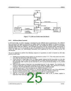
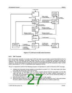
The actions of the CMX910 during a successful transmission will be:
•
•
•
If a Tx State Reset is performed by the µC, the external RF circuits are turned off if necessary
(DAC0 ramped down and ENAB0, 4, 5 negated, assuming the CMX910 has control of these
functions). The Tx State bits in the Tx_Status register then indicate Idle.
As soon as data is written to the Tx_FIFO, the CMX910 will begin assembling a packet for
transmission in its internal message buffer. During this operation, the Tx State indicates Building
message buffer.
When the CMX910 has assembled a complete transmit packet (including training sequence and
HDLC coding), if a Tx Start has already been issued the Tx State changes to Tx pending,
otherwise the Tx State changes to Message buffer ready and waits for Tx Start to be issued
before going to Tx pending.
•
•
When the requested transmit point arrives, the Tx State changes to Tx in progress and the
external transmit circuits are enabled according to how the transmit timing is configured.
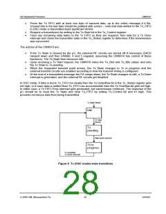
At the end of a transmitted message the PA ramps down. If the Tx_FIFO is empty at this point the
Tx State changes to Idle, a Tx Done interrupt is generated, and the external RF circuits get
disabled. Otherwise the CMX910 assumes a chained message is being sent; it notes the length of
this new message (in Tx_Bits), leaves the external RF circuits enabled, and builds a new
message (during which time Tx State first changes to Chained message for approximately 20µs
then to Building message buffer, then to Tx pending). This message is transmitted in the following
slot, during which time Tx State indicates Tx in progress.
A number of error conditions are checked for during AIS burst mode transmit, each of which causes
transmission to be aborted and a Tx Done interrupt to be generated. The associated Tx States are:
1. Tx aborted, message too long: This happens if the internal message buffer is not big enough for
the HDLC coded data (should not happen in normal operation, as the message buffer is big
enough for a 5-slot message). This condition requires the µC to issue a Tx State Reset.
2. Tx aborted, buffer not ready: This happens if the requested Tx start point arrives before the
message buffer is ready. The µC can then choose to issue a Tx State Reset or to carry on
building the message and reschedule the transmission in another slot.
3. Tx aborted, carrier sensed: This happens if CSTDMA mode is active and a carrier is sensed in
the selected channel at the beginning of the requested transmit slot. Data in the message buffer is
retained, so that the µC can choose to issue a Tx State Reset or to reschedule the transmission
in another slot.
It is not possible to get a Tx_FIFO underflow in AIS burst mode, but writing too quickly could cause an
overflow (this sets the Tx Overflow bit in the Tx_Status register), causing a Tx FIFO Error interrupt to be
generated. The contents of the message buffer will become corrupted by the overflow but the transmit
operation will continue, so the µC should abort the transmission (i.e. reset the Tx State and clear Tx_FIFO
by setting Tx_Control b0 and b1 high).
There is a possibility that the CMX910 will add enough stuffing bits to a message in AIS burst mode to
cause the message to overrun into the next slot, although there is enough padding in the AIS slot
structure to ensure that this occurrence is extremely rare. A minor slot overrun is not normally considered
to be a problem in the AIS system, but if this happens when the CMX910 is attempting to chain a
message in the next slot, it is possible that the CMX910 will miss the chained message start event. This
will cause the chained message to be transmitted one slot too late. To enable the µC to recognise if this
error condition is about to happen, the special command “read_message_length” (section 5.12) is
provided that allows the µC to determine the total number of message bits that have been created in the
CMX910’s internal message buffer. When this special command is issued, the CMX910 waits until the
message buffer is complete then generates a “Special Command Done” interrupt. The µC can then read
the total number of message bits from the SPC_Out0 register; which includes the training sequence,
start/stop flags, CRC checksum and stuffing bits, as well as the actual message bits. The µC should also
take into account the magnitude of any nudge that may be performed during the transmission to
determine whether the message is too long to allow chaining to be attempted.
© 2009 CML Microsystems Plc
26
D/910/6

 CMLMICRO [ CML MICROCIRCUITS ]