AIS Baseband Processor
CMX910
5.5.2 AIS Raw Mode Transmit
In AIS raw mode, transmit data is passed directly from the Tx FIFO to the G(M)FSK modulator. Apart from
the Tx FIFO, no buffering is performed inside the CMX910. The µC must calculate the entire transmitted
message including the training sequence, HDLC processing (start/stop flags, bit stuffing, and CRC
insertion) and NRZI coding. Note: In AIS raw mode, data written to Tx_FIFO is transmitted most
significant bit first. The AIS message structure, however, requires each message byte to be output least
significant bit first. The µC must therefore ensure that during the process of HDLC processing and NRZI
coding that the resulting data bytes are correctly reversed.
The µC is expected to perform the following sequence of operations in order to transmit a data packet in
raw mode:
•
•
Initialise the transmitter timing registers as described in section 5.5.5. (This only needs to be done
once after the device has come out of reset).
Check that the Tx State flags in the Tx_Status register indicate that the transmitter is in the Idle
state and that the Tx FIFO does not contain data from an earlier aborted transmission. If
necessary, the transmitter state machine can be reset and Tx_FIFO can be cleared by writing 1 to
Tx_Control register b1-0.
•
•
•
Write the total number of bits to be transmitted into the Tx_Bits register (not necessarily a multiple
of 8, because of bit stuffing).
Write the timing reference slot number to Tx_Slot (this will most likely be a one or two slots before
the slot in which to transmit data, to allow time for the external Tx circuits to power up).
Prime the Tx FIFO with at least one byte of transmit data, up to the entire message if it fits.
Unused bits in the last byte should be padded with zeroes – note that data written to the Tx_FIFO
in AIS raw mode is transmitted most significant bit first.
•
•
Request a transmission by writing to the Tx Start bit in the Tx_Control register.
Feed any remaining data bytes to the Tx FIFO as they are required, then wait for a Tx Done
interrupt and check the transmitter state in the Tx_Status register to determine if the transmission
was successful.
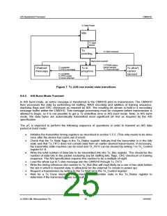
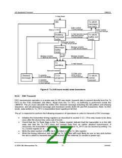
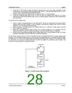
The actions of the CMX910 are:
•
If the Tx State is cleared by the µC, the external RF circuits are turned off if necessary (DAC0
ramped down and then ENAB0, 4 and 5 negated, assuming the CMX910 has control of these
functions). The Tx State then becomes Idle.
•
•
•
Upon receiving a Tx Start request, the CMX910 notes the Tx_Slot and Tx_Bits values and sets
the Tx State to Tx pending.
When the requested transmit point arrives, the Tx State changes to Tx in progress and the
external transmit circuits are enabled according to how the transmit timing is configured.
At the end of a transmitted message the PA ramps down. If the Tx_FIFO is empty at this point the
Tx State changes to Idle, a Tx Done interrupt is generated, and the external RF circuits get
disabled. If the Tx_FIFO is not empty, the CMX910 assumes a chained message is being sent; it
notes the length of this new message (in Tx_Bits), and leaves the external RF circuits enabled.
The Tx State then changes to Chained message, then to Tx in progress when transmission of the
new message begins in the following slot.
Note that if CSTDMA mode is active and a carrier is sensed in the selected channel at the beginning of
the requested transmit slot, the transmission is aborted (Tx State changes to Tx aborted, carrier sensed)
– this causes a Tx Done interrupt to be generated. Data in Tx_FIFO is retained, so the µC can choose to
issue a Tx State Reset and clear Tx_FIFO, or reschedule the transmission in another slot.
In AIS raw mode, if data is fed to Tx_FIFO too slowly then the Tx Underflow bit in the Tx_Status register
gets set high, or if more data is written than Tx_FIFO can accommodate then the Tx Overflow bit gets set
high. In either case, a Tx FIFO Error interrupt gets generated, but transmission continues. The response
of the µC should be to reset the Tx State and clear Tx_FIFO by setting Tx_Control b0 and b1 high. This
prevents erroneous data from being transmitted.
© 2009 CML Microsystems Plc
24
D/910/6

 CMLMICRO [ CML MICROCIRCUITS ]