AIS Baseband Processor
CMX910
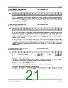
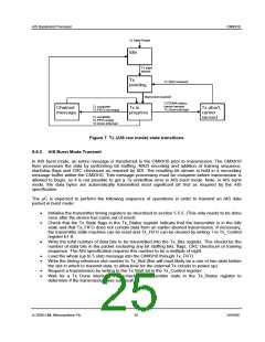
Tx_Slot register: 16-bit write only.
C-BUS Address $23
All bits cleared to 0 on reset.
15
14
13
12
11
10
9
8
7
6
5
4
3
2
1
0
Bit:
Reserved, set to 0000
Slot number in which to begin a transmission sequence
The TX_Slot register must be loaded with the slot number in which a transmit sequence begins.
Typically this will be one or two slots before the slot in which data is to be transmitted, allowing
time for the external RF circuits to power up and stabilise. Further details about transmit timings
are provided in section 5.5.5.
Tx_Bits register: 16-bit write only.
C-BUS Address $24
All bits cleared to 0 on reset.
15
14
13
12
11
10
9
8
7
6
5
4
3
2
1
0
Bit:
Number of bits to transmit
In AIS burst mode, the Tx_Bits register must be programmed with the total number of data bits in
the message excluding all of the training sequence, start/end flags, CRC and bit stuffing bits
added by the CMX910. In AIS burst mode the number loaded into Tx_Bits should always be a
multiple of 8 since the AIS specification requires that the data payload (prior to HDLC coding) be
a whole number of bytes.
In AIS raw mode or DSC mode, the Tx_Bits register must be programmed with the total number
of data bits in the message including all of the training sequence, start/end flags, CRC and bit
stuffing bits (AIS mode) or other data coding bits (DSC mode). This number will generally not be a
multiple of 8, in which case the last byte sent by the µC through the Tx FIFO must be padded with
trailing zeroes.
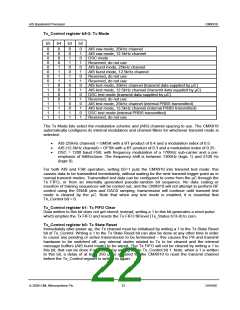
Tx_Control register: 16-bit write only.
C-BUS Address $25
All bits cleared to 0 on reset.
15
14
13
12
11
10
9
8
7
6
5
4
3
2
1
0
Bit:
CS-
TDMA TDMA
enable chan
CS-
Tx
Tx
Tx
Start
Reserved, set to 0000000
Tx Mode
FIFO State
Clear Reset
Tx_Control register b8: Tx Start
Setting b8 = 1 causes a transmission to be triggered in the slot specified in the Tx_Slot register.
This bit will be automatically cleared as soon as the transmission is complete.
Tx_Control register b7: CSTDMA Enable
Set b7 = 1 for Carrier Sensing TDMA operation, b7 = 0 for normal operation.
Tx_Control register b6: CSTDMA Channel Select
Determines which receive channel is examined for presence of a carrier before the transmit
operation starts. Set b6 = 1 to select CSTDMA operation on “Channel 2”, or b6 = 0 for operation
on “Channel 1”.
© 2009 CML Microsystems Plc
21
D/910/6

 CMLMICRO [ CML MICROCIRCUITS ]