AIS Baseband Processor
CMX910
5.4.2 Auto Nudge
Two auto nudge modes are provided which assist the µC with the initial synchronisation of the slot and
sample counters, and allow the CMX910 to subsequently keep the sample counter aligned without further
intervention. This requires an accurate UTC1PPS signal to be applied to the CMX910:
Auto nudge acquire (Slot_Sample_Control b1-0 = 01). This mode can be used for initial counter
synchronisation after a device reset or in the case where the slot and sample counters have
become grossly misaligned for some reason. Auto nudge acquire should be enabled when the
CMX910 has just received a UTC1PPS rising edge from an “even” UTC second, which means
that the next UTC1PPS rising edge will be an “odd” second. The CMX910 will calculate the error
in the sample counter latched in from the “even” UTC second and will apply the required
correction to the sample counter at the next Nudge_Trigger point. A Nudge_Done interrupt is then
generated, indicating that sample counter alignment has been achieved.
Auto nudge track (Slot_Sample_Control b1-0 = 10). In this mode, the CMX910 calculates the
correction needed for the sample counter once per second (on the rising edge of UTC1PPS).
“Odd” and “even” UTC seconds are treated differently: if 320 ≤ Sample_Count < 960 when the
rising edge of UTC1PPS occurs, the CMX910 assumes it to be an “odd” UTC second and
calculates a sample nudge value of (640 - Sample_Count). Otherwise, the sample nudge value is
calculated as (-1 × Sample_Count). This calculated value (or ±Max_Auto_Nudge, whichever is
smaller in magnitude) is then added to the sample counter at the next Nudge_Trigger point. Note:
if the µC writes a non-zero value to the Slot_Nudge register when in auto nudge track mode, this
will be added to the slot counter at the same time that the sample counter value is updated. The
Slot_Nudge register gets auto-cleared after being used which causes a Nudge_Done interrupt,
otherwise Nudge Done interrupts are not generated in auto nudge track mode.
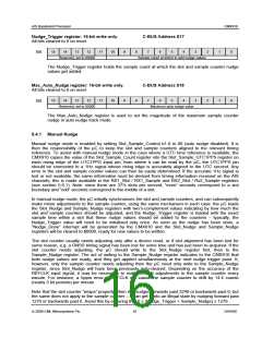
The Max_Auto_Nudge register is used to limit the magnitude of the allowed nudge in order to avoid
potential timing problems. The Max_Auto_Nudge register is ignored in manual nudge and auto nudge
acquire mode.
The typical sequence of events that the µC must perform to achieve and retain slot and sample counter
synchronisation (using auto nudge) is shown below:
a) If the device has just come out of reset, initialise Nudge_Trigger (see section 5.4.4) and
Max_Auto_Nudge registers.
b) Wait for an even UTC second to occur, then put the CMX910 into auto nudge acquire mode.
c) Wait for a Nudge Done interrupt, then put the CMX910 into auto nudge track mode.
d) Wait for the next UTC1PPS rising edge, then read the Slot_Sample_UTC1PPS register, and use
this to determine the error in the slot counter (the sample counter should be correctly aligned at
this point). Write the necessary correction to the Slot_Nudge register.
e) Wait for a Nudge Done interrupt. Both slot and sample counters will now be correctly aligned, and
the µC can proceed with AIS Rx and Tx operations, as required. No further Nudge Done
interrupts will be generated while in auto nudge track mode unless Slot_Nudge is written to again.
f) Continue monitoring the UTC time signal. If the CMX910 slot and sample counters become
misaligned for any reason (for instance, when a UTC leap second occurs), the µC must perform
another synchronisation sequence. If a direct UTC time signal becomes lost for any reason, then
the µC must switch the CMX910 to manual nudge mode and maintain synchronisation to a UTC
indirect source or an appropriate base station.
5.4.3 Sleep Mode
The Rx1 and Rx2 channels are individually configurable using bits in the receiver control registers
Rx1_Control and Rx2_Control. When enabled for AIS reception, it is possible to reduce power
consumption significantly by configuring the CMX910 to automatically turn off its internal receiver circuits
© 2009 CML Microsystems Plc
17
D/910/6

 CMLMICRO [ CML MICROCIRCUITS ]