AIS Baseband Processor
CMX910
and negate the ENAB1 or ENAB2 pins during inactive slots. This will happen when sleep mode is enabled
and a valid training sequence and start flag has not been detected at the beginning of a slot, i.e. there is
no data to demodulate. The Rx1 and Rx2 circuits will automatically power up again at the end of an
inactive slot, ready to search for another training sequence in the next slot. Note that when sleep mode is
enabled, the Rx1 and Rx2 channels power down independently; it is possible for either, or both, channels
to be powered down in any particular slot, depending on the activity in the channels.
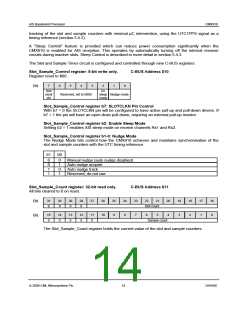
The sleep mode feature is enabled by setting bit 2 of the Slot_Sample_Control register. The period within
an inactive slot that the Rx circuits are to be disabled must be programmed by the µC into the
Sleep_Sample and Wakeup_Sample registers: sleep mode starts within an inactive slot when the sample
counter equals the value in the Sleep_Sample register and finishes when the sample counter
subsequently reaches the value in the Wakeup_Sample register.
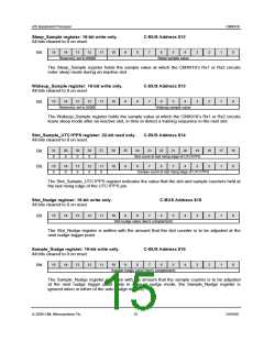
The value in the Sleep_Sample register should be loaded with a sample number just beyond the latest
point in a slot that the training sequence and start flag could occur. Account must be taken of the
maximum remote transmitter timing error and distance delay, as well as the local receiver timing error and
filter delays.
The value in the Wakeup_Sample register can be chosen to be towards the end of the inactive slot, or
shortly after the beginning of the next slot. When determining the value to write to Wakeup_Sample,
account must be taken of the maximum remote transmitter timing error, as well as the local receiver timing
error and receive circuit start-up time.
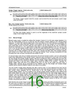
5.4.4 Selecting the Nudge_Trigger Value
Whether the sample counter tracking is performed using manual nudge mode or auto nudge mode, the
value written to the Nudge_Trigger register needs to be chosen carefully to avoid confusing the transmit
or receive event timing.
All transmission events are timed relative to a point before the start of the slot in which a message is to be
transmitted. This point is defined by the sample value loaded into the Tx_Start parameter in the Tx event
sequence table (described in section 5.5.5). At this point the transmission is deemed to have started. All
subsequent transmit events within the slot are timed relative to this Tx_Start point. This means that once
transmission starts, all subsequent events (e.g. PA ramping, start of modulation) occur with the correct
relative timing until the whole slot has been transmitted, irrespective of any change to Sample_Count.
Therefore the only transmit problem that may occur is if a sample counter nudge causes the value in
Sample_Count to skip past the point defined by Tx_Start, which would cause the event to be missed. This
can be prevented by limiting the maximum allowed nudge value and ensuring that the Nudge_Trigger is
far enough away from Tx_Start that Sample_Count can never skip past the Tx_Start event.
Similarly, all receive events are timed relative to the point that a start flag is detected after a valid training
sequence, so once reception of a data packet begins, changes to Sample_Count will not affect the
received data. The µC should be aware, however, that any values reported in the Rx1_Sample, Rx1_Slot,
Rx2_Sample and Rx2_Slot registers are the values that were in the slot and sample counters at the time
that the Rx1 and Rx2 start flags were detected. To avoid confusion it is therefore advisable to ensure that
Nudge_Trigger is sufficiently far away from the likely position of a start flag.
Also, if the receive channels are configured to sleep during inactive slots (i.e. Slot_Sample_Control b2 =
1), the Nudge_Trigger value must be far enough away from Sleep_Sample and Wakeup_Sample values
that the Sample_Count can never skip past these events (this would cause intermittent receive channel
malfunction).
A further restriction is that the value added to the sample counter must not cause an overflow. This means
that in manual nudge mode the µC should ensure that 0 ≤ (Nudge_Trigger + Sample_Nudge) ≤ 1279. In
auto nudge track mode, ensure that 0 ≤ (Nudge_Trigger ± Max_Auto_Nudge) ≤ 1279.
© 2009 CML Microsystems Plc
18
D/910/6

 CMLMICRO [ CML MICROCIRCUITS ]