AIS Baseband Processor
CMX910
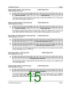
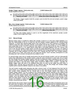
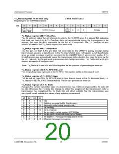
Nudge_Trigger register: 16-bit write only.
C-BUS Address $17
All bits cleared to 0 on reset.
15
14
13
12
11
10
9
8
7
6
5
4
3
2
1
0
Bit:
Reserved, set to 00000
Sample count at which to add nudge values
The Nudge_Trigger register holds the sample count at which the slot and sample counter nudge
values get added.
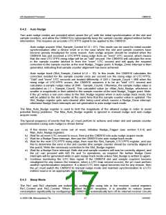
Max_Auto_Nudge register: 16-bit write only.
C-BUS Address $18
All bits cleared to 0 on reset.
15
14
13
12
11
10
9
8
7
6
5
4
3
2
1
0
Bit:
Reserved, set to 00000
Maximum auto nudge value
The Max_Auto_Nudge register is used to set the magnitude of the maximum sample counter
nudge in auto nudge track mode.
5.4.1 Manual Nudge
Manual nudge mode is enabled by setting Slot_Sample_Control b1-0 to 00 (auto nudge disabled). It is
then the responsibility of the µC to keep the slot and sample counters aligned to the relevant timing
reference. To assist with manual nudge mode in the case where a UTC time reference is available, the
CMX910 copies the value of the Slot_Sample_Count register into the Slot_Sample_UTC1PPS register on
each rising edge of the UTC1PPS input pin, from where it can be read by the µC; the UTC1PPS pin
should be connected to a 1Hz signal whose rising edge is accurately aligned to the UTC second. Any
error in the slot and sample counter values can then be easily determined. If the accurate 1Hz signal is
lost or not available, the same information must be derived from timing information received on the AIS
channels; this is made available in the RX1_Slot / RX1_Sample and RX2_Slot / Rx2_Sample registers
(see section 5.6.1). Note: since there are 37½ slots per second, “even” seconds correspond to a slot
boundary and “odd” seconds correspond to the middle of a slot.
In manual nudge mode, the µC initially synchronises the slot and sample counters, and can subsequently
make minor adjustments to the sample counter, using the same mechanism in each case: the µC loads
the Slot_Nudge and Sample_Nudge registers with two’s-complement values indicating by how much the
slot and sample counters should be adjusted, and the Nudge_Trigger register is loaded with the exact
sample time within a slot that these nudge values should be added to the counters – typically, the
Nudge_Trigger value will need to be initialised only once. As soon as the nudge has been done, a
“Nudge_Done” interrupt will be generated by the CMX910 and the Slot_Nudge and Sample_Nudge
registers will be cleared to $0000, ready for new values to be written.
The slot counter usually needs adjusting only after a device reset, or if slot alignment has been lost for
some reason, e.g. a GNSS timing signal has been lost for some time and has just been re-acquired. If the
slot counter needs adjusting, the µC should write to the Slot_Nudge register first, then to the
Sample_Nudge register. The act of writing to the Sample_Nudge register indicates to the CMX910 that
both nudge values are ready, and they get applied simultaneously at the next nudge trigger point. If,
however, only the sample counter needs adjusting then the µC need only write to the Sample_Nudge
register, since Slot_Nudge will have been previously auto-cleared. Depending on the accuracy of the
REFCLK input signal, it may be necessary to make several adjustments to the sample counter every
minute. For instance, a 5ppm error in REFCLK will cause the sample counter to drift by 14.4 counts
(nearly 3 bit periods) per minute.
Note that the slot counter “wraps” properly when it is nudged forwards past 2249 or backwards past 0, but
the same does not apply to the sample counter – it can get it into an illegal state by nudging forward past
1279 or backwards past 0. Avoid this by ensuring that 0 ≤ (Nudge_Trigger + Sample_Nudge) ≤ 1279.
© 2009 CML Microsystems Plc
16
D/910/6

 CMLMICRO [ CML MICROCIRCUITS ]