AIS Baseband Processor
CMX910
5.4
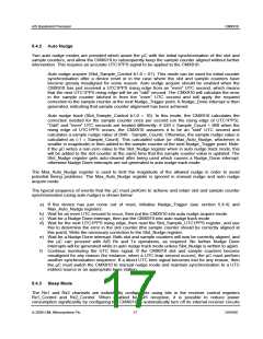
Slot and Sample Timer
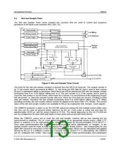
The Slot and Sample Timer circuit contains two counters that are used to control and sequence
operations in the three main channels (Rx1, Rx2, Tx).
C-BUS
Sleep_Sample
Wakeup_Sample
Nudge_Trigger
Comparator
A=B
Comparator
A=B
Comparator
A=B
Slot_Sample_Control
Max_Auto_Nudge
Slot and Sample
Nudge Control Logic
Slot_Nudge
Sample_Nudge
A+B
A+B
Nudge
Sample Counter
(11 bit)
Slot Counter
(12 bit)
Overflow
48
kHz
pin
ctrl
Slot_Sample_Count
SLOTCLKN
UTC1PPS
Load
Slot_Sample_UTC1PPS
Figure 5 Slot and Sample Timer Circuit
The clock for the slot and sample counters is derived from the REFCLK input pin. The sample counter is
an 11 bit counter which increments at 48kHz, i.e. five times per AIS data bit, and is used to time various
Rx and Tx operations within a slot period. Since there are 256 bit periods per AIS slot, the sample counter
increments from 0 to 1279 before rolling over to 0. The slot counter is a 12 bit counter and is used to
count the slot number in an AIS frame, which lasts for a minute. It is incremented at the beginning of each
AIS slot period, i.e. when the sample counter rolls over. There are 37½ slots per second, resulting in 2250
slots per minute. Therefore the slot counter increments from 0 to 2249 before rolling over to 0. When
operating correctly, the slot counter rollover should be aligned to the start of the UTC minute. The current
value of the slot and sample counters are available to the µC by reading the Slot_Sample_Count register.
The CMX910 produces a pulse on its SLOTCLKN output pin during the first sample period within each
slot, this can be used as general timing reference by the µC. Each pulse is active low and lasts for
approximately 20.83 µs, and the pulses repeat at 37.5Hz. The signal appearing on the SLOTCLKN pin
can be configured to be open-drain pull-down or have active pull-up and pull-down drivers.
When the CMX910 comes out of reset the slot and sample counters will be free running but not
synchronised to anything. The µC must synchronise them to an appropriate timing source, either UTC
(direct or indirect) or to an appropriate base station as required by Recommendation ITU-R M1371-1.
Once initial synchronisation has been established, occasional minor adjustments, or “nudges”, to the
sample counter must be made to keep it locked to the chosen timing source – this compensates for any
slight drift caused by inaccuracy in the REFCLK frequency. Nudge values can be calculated and applied
directly by the µC in a software control loop (“manual nudge”, section 5.4.1). Alternatively, the CMX910
can be configured into certain “auto nudge” modes to establish initial synchronisation and subsequent
© 2009 CML Microsystems Plc
13
D/910/6

 CMLMICRO [ CML MICROCIRCUITS ]