CS2000-OTP
It is important to note that Auto R-Mod (if enabled) is applied in addition to any R-Mod already selected
by the RModSel[1:0] modal parameter and is used to calculate the Effective Ratio (see Section 5.4.5 on
page 16).
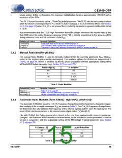
Auto R-Mod can be used to generate the appropriate oversampling clock (MCLK) for audio A/D and D/A
converters. For example, if the clock applied to CLK_IN is the audio sample rate, Fs (also known as the
word, frame or Left/Right clock), and SysClk is 12.288 MHz (REF_CLK = 12.288 MHz with RefClkDiv[1:0]
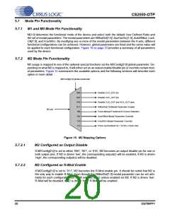
set to ‘10’), FsDetect[1:0] would then reflect the frequency range of the audio sample rate. An R of 512
UD
generates the audio oversampling clocks as shown in Table 4.
Inferred Audio Sample Rate Speed Mode (used for Audio Oversampling
FsDetect[1:0]
when SysClk = 12.288 MHz
audio converters)
Clock
512 x
256 x
128 x
00
01
10
< 54.8 kHz
Single Speed
54.8 kHz to 128 kHz
> 128 kHz
Double Speed
Quad Speed
Table 4. Example Audio Oversampling Clock Generation from CLK_IN
Referenced Control
Parameter Definition
Ratio 0-3................................“Ratio 0 - 3” on page 24
RModSel[1:0] ........................“R-Mod Selection (RModSel[1:0])” section on page 23
AutoRMod .............................“Auto R-Modifier Enable (AutoRMod)” on page 24
M2Config[2:0]........................“M2 Pin Configuration (M2Config[2:0])” on page 26
5.4.5
Effective Ratio (R
)
EFF
The Effective Ratio (R
) is an internal calculation comprised of R and the appropriate modifiers, as
EFF
UD
previously described. R
is calculated as follows:
EFF
Frequency Synthesizer (Static Ratio) Mode: R
= RUD • R-Mod
EFF
Hybrid PLL (Dynamic Ratio) Mode: R
= RUD • R-Mod • Auto R-Mod
EFF
To simplify operation the device handles some of the ratio calculation functions automatically (such as
when the internal timing reference clock divider is set). For this reason, the Effective Ratio does not need
to be altered to account for internal dividers.
Ratio modifiers which would produce an overflow or truncation of R
should not be used. In all cases,
EFF
the maximum and minimum allowable values for R
are dictated by the frequency limits for both the
EFF
input and output clocks as shown in the “AC Electrical Characteristics” on page 7.
Selection of the user defined ratio from the four stored ratios is made by using the M[1:0] pins unless auto
clock switching is enabled in which case the LockClk[1:0] modal parameter also selects the ratio (see
“Fractional-N Source Selection” on page 16).
Referenced Control
Parameter Definition
M[1:0] pins.............................“M1 and M0 Mode Pin Functionality” on page 20
LockClk[1:0] ..........................“Lock Clock Ratio (LockClk[1:0])” section on page 24
5.4.6
Fractional-N Source Selection
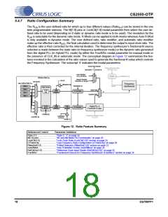
To select between the static ratio based Frequency Synthesizer Mode and the dynamic ratio based Hybrid
PLL Mode, the source for the fractional-N value for the Frequency Synthesizer must be changed. The
Fractional-N value can either be sourced directly from the Effective Ratio (static ratio) or from the output
of the Digital PLL (dynamic ratio) (see Figure 12 on page 18). The setting of this function can be made
manual or automatically depending on the presence of CLK_IN.
16
DS758PP1

 CIRRUS [ CIRRUS LOGIC ]