CS2000-OTP
binary portion. In this configuration, the maximum multiplication factor is approximately 1,048,575 with a
resolution of 244 PPM.
The 20.12 format is enabled by the LFRatioCfg global parameter. The 20.12 ratio format is only available
when the device is running in Hybrid PLL Mode. In Auto Fractional-N Source Selection Mode (see section
5.4.6.2 on page 17) when CLK_IN is not present the LFRatioCfg parameter is ignored and the ratio format
is 12.20.
It is recommended that the 12.20 High-Resolution format be utilized whenever the desired ratio is less
than 4096 since the output frequency accuracy of the PLL is directly proportional to the accuracy of the
timing reference clock and the resolution of the R
.
UD
Referenced Control
Parameter Definition
LockClk[1:0] ..........................“Lock Clock Ratio (LockClk[1:0])” section on page 24
LFRatioCfg............................“Low-Frequency Ratio Configuration (LFRatioCfg)” on page 26
FracNSrc...............................“Fractional-N Source for Frequency Synthesizer (FracNSrc)” section on page 24
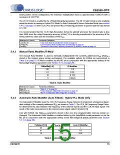
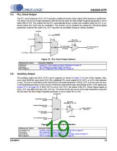
5.4.3
Manual Ratio Modifier (R-Mod)
The manual Ratio Modifier is used to internally multiply/divide the currently addressed R
(Ratio
0-3
UD
stored in the register space remain unchanged). The available options for R-Mod are summarized in
Table 2 on page 15. R-Mod is enabled via the M2 pin in conjunction with the appropriate setting of the
M2Config[2:0] global parameter (see Section 5.7.2 on page 20).
RModSel[1:0]
R Modifier
0.5
00
01
10
11
0.25
0.125
0.0625
Table 2. Ratio Modifier
Referenced Control
Parameter Definition
Ratio 0-3................................“Ratio 0 - 3” on page 24
RModSel[1:0] ........................“R-Mod Selection (RModSel[1:0])” section on page 23
M2Config[2:0]........................“M2 Pin Configuration (M2Config[2:0])” on page 26
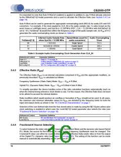
5.4.4
Automatic Ratio Modifier (Auto R-Mod) - Hybrid PLL Mode Only
The Automatic R-Modifier uses the CLK_IN Frequency Range Detector to implement a frequency depen-
dent multiply of the currently addressed R as shown in Table 3. The CLK_IN Frequency Range Detec-
UD
tor determines the ratio between the frequency of the internal SysClk and the CLK_IN input signal. The
result of the ratio measurement is the internal status signal called FsDetect[1:0].
Like with R-Mod, the Ratio
parameters stored in the one time programmable memory remain un-
0-3
changed. The Automatic Ratio Modifier is enabled either by the AutoRMod modal parameter or via the
M2 pin in conjunction with the appropriate setting of the M2Config[2:0] global parameter (see Section
5.7.2 on page 20).
f
/ f
FsDetect[1:0]
Auto R Modifier
SysClk CLK_IN
00
01
10
> 224
96 - 224
< 96
1
0.5
0.25
Table 3. Automatic Ratio Modifier
DS758PP1
15

 CIRRUS [ CIRRUS LOGIC ]