CS2000-OTP
CLK_OUT signal in order to maintain phase alignment. For these applications, it is advised to experiment
with the loop bandwidth settings and choose the lowest bandwidth setting that does not produce system
timing errors due to wandering between the clocks and data synchronous to the CLK_IN domain and
those synchronous to the PLL_OUT domain.
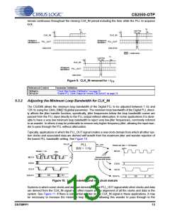
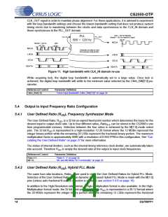
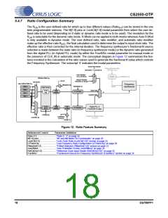
Jitter > 128 Hz Rejected
Wander < 128 Hz Passed to Output
PLL
CLK_IN
PLL_OUT
BW = 128 Hz
MCLK
Wander < 128 Hz
Jitter
MCLK
LRCK
SCLK
or
Subclocks and data re-used
from previous clock domain.
LRCK
SCLK
SDATA
D0
D1
SDATA
D0
D1
Figure 11. High bandwidth with CLK_IN domain re-use
While acquiring lock, the digital loop bandwidth is automatically set to a large value. Once lock is
achieved, the digital loop bandwidth will settle to the minimum value selected by the ClkIn_BW[2:0] pa-
rameter.
Referenced Control
Parameter Definition
ClkIn_BW[2:0] .......................“Clock Input Bandwidth (ClkIn_BW[2:0])” on page 26
5.4
Output to Input Frequency Ratio Configuration
5.4.1
User Defined Ratio (R ), Frequency Synthesizer Mode
UD
The User Defined Ratio, R , is a 32-bit un-signed fixed-point number which determines the basis for the
UD
desired input to output clock ratio. Up to four different ratios, Ratio , can be stored in the CS2000’s one
0-3
time programmable memory. Selection between the four ratios is achieved by the M[1:0] mode select
pins. The 32-bit R is represented in a high-resolution 12.20 format where the 12 MSBs represent the
UD
integer binary portion while the remaining 20 LSBs represent the fractional binary portion. The maximum
multiplication factor is approximately 4096 with a resolution of 0.954 PPM in this configuration. See “Cal-
culating the User Defined Ratio” on page 27 for more information.
The status of internal dividers, such as the internal timing reference clock divider, are automatically taken
into account. Therefore R is simply the desired ratio of the output to input clock frequencies.
UD
Referenced Control
Parameter Definition
Ratio 0-3................................“Ratio 0 - 3” on page 24
M[1:0] ....................................“M1 and M0 Mode Pin Functionality” on page 20
5.4.2
User Defined Ratio (R ), Hybrid PLL Mode
UD
The same four ratio locations, Ratio , are used to store the User Defined Ratios for Hybrid PLL Mode.
0-3
Selection of the User Defined Ratio for the dynamic ratio based Hybrid PLL Mode is made with the M[1:0]
pins (unless auto fractional N source selection is enabled; see section 5.4.6 on page 16).
In addition to the High-Resolution ratio format, a High-Multiplication format is also available. In the High-
Multiplication format mode, the 32-bit fixed-point number for R is represented in a 20.12 format where
UD
the 20 MSBs represent the integer binary portion while the remaining 12 LSBs represent the fractional
14
DS758PP1

 CIRRUS [ CIRRUS LOGIC ]