CS2000-OTP
5.5
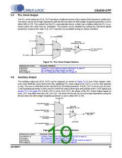
PLL Clock Output
The PLL clock output pin (CLK_OUT) provides a buffered version of the output of the frequency synthesizer.
The driver can be set to high-impedance with the M2 pin when the M2Config[1:0] global parameter is set to
either 000 or 010. The output from the PLL automatically drives a static low condition while the PLL is un-
locked (when the clock may be unreliable). This feature can be disabled by setting the ClkOutUnl global
parameter, however the state CLK_OUT may then be unreliable during an unlock condition.
ClkOutUnl
PLL Locked/Unlocked
0
0
M2 pin with
M2Config[1:0] = 000, 010
0
2:1 Mux
1
PLL Clock Output
PLLClkOut
PLL Clock Output Pin
(CLK_OUT)
2:1 Mux
PLL Output
1
Figure 13. PLL Clock Output Options
Referenced Control
Parameter Definition
ClkOutUnl..............................“Enable PLL Clock Output on Unlock (ClkOutUnl)” on page 25
ClkOutDis..............................“M2 Configured as Output Disable” on page 20
M2Config[2:0]........................“M2 Pin Configuration (M2Config[2:0])” on page 26
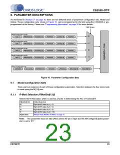
5.6
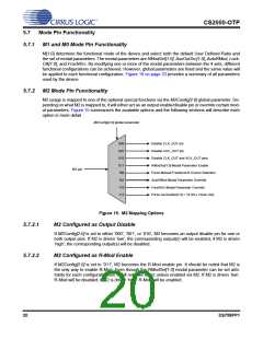
Auxiliary Output
The auxiliary output pin (AUX_OUT) can be mapped, as shown in Figure 14, to one of four signals: refer-
ence clock (RefClk), input clock (CLK_IN), additional PLL clock output (CLK_OUT), or a PLL lock indicator
(Lock). The mux is controlled via the AuxOutSrc[1:0] modal parameter. If AUX_OUT is set to Lock, the Aux-
LockCfg global parameter is then used to control the output driver type and polarity of the LOCK signal (see
section 6.3.2 on page 25). If AUX_OUT is set to CLK_OUT, the phase of the PLL Clock Output signal on
AUX_OUT may differ from the CLK_OUT pin. The driver for the pin can be set to high-impedance using the
M2 pin when the M2Config[1:0] global parameter is set to either 001 or 010.
AuxOutSrc[1:0]
Timing Reference Clock
(RefClk)
M2 pin with
M2Config[1:0] = 001, 010
Frequency Reference Clock
(CLK_IN)
Auxiliary Output Pin
(AUX_OUT)
4:1 Mux
PLL Clock Output
(PLLClkOut)
AuxLockCfg
PLL Lock/Unlock Indication
(Lock)
Figure 14. Auxiliary Output Selection
Referenced Control
Parameter Definition
AuxOutSrc[1:0]......................“Auxiliary Output Source Selection (AuxOutSrc[1:0])” on page 24
AuxOutDis.............................“M2 Configured as Output Disable” on page 20
AuxLockCfg...........................“AUX PLL Lock Output Configuration (AuxLockCfg)” section on page 25
M2Config[2:0]........................“M2 Pin Configuration (M2Config[2:0])” on page 26
DS758PP1
19

 CIRRUS [ CIRRUS LOGIC ]