CS2000-OTP
5. APPLICATIONS
5.1
One Time Programmability
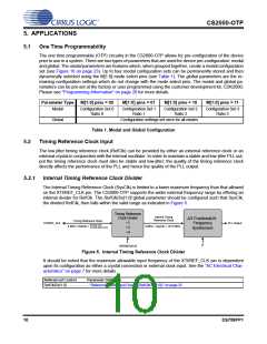
The one time programmable (OTP) circuitry in the CS2000-OTP allows for pre-configuration of the device
prior to use in a system. There are two types of parameters that are used for device pre-configuration: modal
and global. The modal parameters are features which, when grouped together, create a modal configuration
set (see Figure 16 on page 23). Up to four modal configuration sets can be permanently stored and then
dynamically selected using the M[1:0] mode select pins (see Table 1). The global parameters are the re-
maining configuration settings which do not change with the mode select pins. The modal and global pa-
rameters can be pre-set at the factory or user programmed using the customer development kit, CDK2000;
Please see “Programming Information” on page 28 for more details.
Parameter Type
M[1:0] pins = 00
M[1:0] pins = 01
M[1:0] pins = 10
M[1:0] pins = 11
Modal
Configuration Set 0
Ratio 0
Configuration Set 1
Ratio 1
Configuration Set 2
Ratio 2
Configuration Set 3
Ratio 3
Global
Configuration settings set once for all modes.
Table 1. Modal and Global Configuration
5.2
Timing Reference Clock Input
The low jitter timing reference clock (RefClk) can be provided by either an external reference clock or an
external crystal in conjunction with the internal oscillator. In order to maintain a stable and low-jitter PLL out-
put the timing reference clock must also be stable and low-jitter; the quality of the timing reference clock
directly affects the performance of the PLL and hence the quality of the PLL output.
5.2.1
Internal Timing Reference Clock Divider
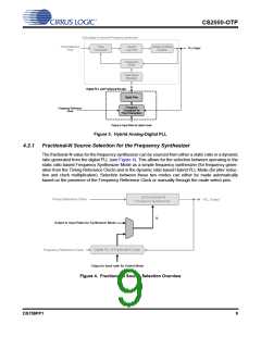
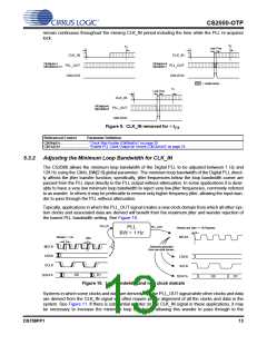
The Internal Timing Reference Clock (SysClk) is limited to a lower maximum frequency than that allowed
on the XTI/REF_CLK pin. The CS2000-OTP supports the wider external frequency range by offering an
internal divider for RefClk. The RefClkDiv[1:0] global parameter should be configured such that SysClk,
the divided RefClk, then falls within the valid range as indicated in Figure 5.
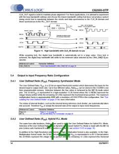
Timing Reference
Internal Timing
Clock Divider
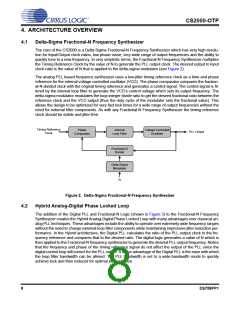
Fractional-N
Frequency
Synthesizer
Reference Clock
Timing Reference Clock
÷1
÷2
÷4
XTI/REF_CLK
PLL Output
50 MHz (XTI)
8 MHz < RefClk <
8 MHz < SysClk < 18.75 MHz
75 MHz (REF_CLK)
N
RefClkDiv[1:0]
Figure 5. Internal Timing Reference Clock Divider
It should be noted that the maximum allowable input frequency of the XTI/REF_CLK pin is dependent
upon its configuration as either a crystal connection or external clock input. See the “AC Electrical Char-
acteristics” on page 7 for more details.
Referenced Control
Parameter Definition
RefClkDiv[1:0] .......................“Reference Clock Input Divider (RefClkDiv[1:0])” on page 25
10
DS758PP1

 CIRRUS [ CIRRUS LOGIC ]