write enable instruction to be executed to write data to the
EEPROM. It is unlikely that this would accidentally be
written to the EEPROM device and then be followed by a
valid write operation. Further security can be obtained by
using an SPI EEPROM device that has internal write-protect
control bits. These bits are nonvolatile and must be cleared
before write operations are allowed.
EEPROM DATA STORAGE
The XTR108 automatically reads data from an SPI-compat-
ible EEPROM device. The models 25C040 from MicroChip
and the AT25010 from Atmel have been tested and are
known to work. Equivalent devices with an SPI interface can
be expected to work. The XTR108 will read data from
addresses 4 through 15 of the EEPROM. The address in the
EEPROM is the same as the address for the corresponding
data in the XTR108. The XTR108 will not write data to the
EEPROM. The external calibration controller is responsible
for writing data to the EEPROM.
SURGE PROTECTION
Remote connections to current transmitters can sometimes
be subjected to voltage surges. It is prudent to limit the
maximum surge voltage applied to the XTR108 with various
zener diodes and surge-clamping diodes specially designed
for this purpose. Since the maximum voltage on the XTR108
loop is limited by the external MOSFET breakdown voltage,
usually more than 200V, the requirement to the clamping
devices are not very strict. For example, a 50V protection
diode will assure proper transmitter operation at normal loop
voltages without significant leakage yet provide an appro-
priate level of protection against voltage surges. In case of
prolonged (seconds and longer) overvoltage, lower voltage
clamps may be used to limit the power dissipation on the
transmitter.
CHECKSUM FUNCTION
To validate the data from the EEPROM device, the XTR108
calculates a checksum on the incoming serial-data stream
during each write operation. The value written to the EEPROM
that will be transferred to register 15 during an EEPROM read
operation must be such that the sum of the data in registers 4
through 15 totals 0xFF (255). The sum is calculated by
performing an add/accumulate function on all of the data
bytes of a read operation. An end-around carry is used during
the add/accumulate operation. If a carry-out was generated in
the previous add operation, it is used as a carry-in for the next
add operation for the checksum operation. The following code
shows how the value of register 15 could be calculated:
Most surge-protection zener diodes have a diode character-
istic in the forward direction that will conduct excessive
current, possibly damaging receiving-side circuitry if the
loop connections are reversed. If a surge protection diode is
used, a series diode or diode bridge should be used for
protection against reversed connections.
Sum = 0
FOR Index = 4 TO 14
Sum = Sum + Data [Index]
IF Sum > 255 THEN
Sum = Sum – 255
NEXT Index
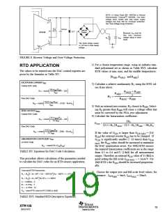
REVERSE-VOLTAGE PROTECTION
The XTR108’s low compliance rating (7.5V) permits the
use of various voltage protection methods without compro-
mising operating range. Figure 8 shows a diode bridge
circuit which allows normal operation even when the volt-
age connection lines are reversed. The bridge causes a two
diode drop (approximately 1.4V) loss in loop supply volt-
age. This results in a compliance voltage of approximately
9V—satisfactory for most applications. If 1.4V drop in loop
supply is too much, a diode can be inserted in series with the
loop supply voltage and the V+ pin. This protects against
reverse output connection lines with only a 0.7V loss in loop
supply voltage.
Data [15] = 255 – Sum
For a test or calibration operation, it may be necessary to
write to a few select registers. This may be accomplished
without writing to register 15. To accomplish this, write to
the necessary registers and release CS1. There is no need to
update register 15.
If the command is to disable the automatic read-back func-
tion by setting the RDB bit in register 4, it is necessary to
rewrite the entire register set data with a correct checksum
value in register 15. The automatic read-back mode will be
disabled upon successful checksum operation.
RADIO FREQUENCY INTERFERENCE
The long wire lengths of current loops invite radio frequency
interference. RF energy can be rectified by the sensitive
input circuitry of the XTR108 causing errors. This generally
appears as an unstable output current that varies with the
position of loop supply or input wiring.
The checksum error flag is also cleared when the XTR108
is reset (i.e.: at power ON). Write operations that do not
write to the checksum register will have no effect on the
checksum error flag. By locating the checksum register after
the last configuration register and including the checksum
register in the EEPROM read operation, the data is validated
by the checksum function.
If the RTD sensor is remotely located, the interference may
enter at the input terminals. For integrated transmitter as-
semblies with short connection to the sensor, the interfer-
ence more likely comes from the current loop connections.
EEPROM DATA SECURITY
Bypass capacitors on the input reduce or eliminate this input
interference. Connect these bypass capacitors to the IRET
terminal, see Figure 9. Although the DC voltage at the IRET
terminal is not equal to 0V (at the loop supply, VPS) this
circuit point can be considered the transmitter’s “ground.”
The 0.01µF capacitor connected between VLOOP and IO may
help minimize output interference.
Since the data in the EEPROM directly affects the analog
output of the XTR108, the data in the EEPROM needs to be
secure from accidental write operations. SPI EEPROM de-
vices have a write-protect function on one of the pins. An
additional connection to the calibration controller would be
required if the write-protect pin is used to prevent accidental
write operations. SPI EEPROM devices require a special
XTR108
18
SBOS187C
www.ti.com

 BB [ BURR-BROWN CORPORATION ]