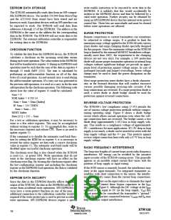
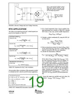
NOTE: (1) Zener Diode 36V: 1N4753A or General
Semiconductor TransorbTM 1N6286A. Use lower
voltage zener diodes with loop power supply
voltages less than 30V for increased protection.
See “Over-Voltage Surge Protection.”
10
V+
0.01µF
1N4148
Diodes
(1)
14
13
D1
XTR108
Maximum VPS must be
less than minimum
voltage rating of zener
RL
VPS
diode.
IO
11
The diode bridge causes
a 1.4V loss in loop supply
voltage.
IRET
12
FIGURE 8. Reverse Voltage and Over-Voltage Protection.
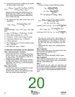
1) For a chosen temperature range, using an industry-stan-
dard polynomial set as shown in Table XVI, calculate
RTD values at min, max, and the middle temperatures:
RTD APPLICATION
The values to be entered into the DAC control registers are
given by the formulas in Table XV.
R
MIN, RMAX, and RMID
(
)
EXCITATION CURRENT IREF
2) Calculate a relative nonlinearity BV using the RTD val-
ues from above:
Coarse DAC code
64 • IREFRSET
N11 = round
− 320
R
+ R
MIN
VREF
MAX
R
–
MID
2
B
=
V
Fine DAC Code
N10 = round
R
– R
MAX
MIN
1024 • IREFRSET
− 5120 − 16 • N11
VREF
3) Pick an external zero resistor, RZ closest to RMIN. Select-
ing RZ greater than RMIN will cause a voltage offset that
must be corrected by the PGA zero adjustment.
4) Calculate the linearization coefficient::
ZERO OUTPUT IZERO
Coarse DAC Code
32 • IZERORVI
N13 = round
− 140
5 • VREF
2BV
GLIN
=
0.5 + B
R
– 0.5 – B
R
– 2BVRZ
MIN
(
)
(
)
V
MAX
V
Fine DAC Code
512 • IZERORVI
5 • VREF
N12 = round
− 2240 − 16 • N13
If the value of GLIN is larger than GLIN MAX = (16/
RLIN) the external resistor RLIN has to be changed. If
GLIN is significantly smaller (> 10 times) than GLIN
MAX, the RLIN value should be increased to minimize
the DAC quantization errors. For 100Ω RTD sensors
the required linearization coefficients are in the range
from 0.3 to 0.6 mA/V (1/kΩ) for all measurement
ranges. Therefore an external RLIN value of 15.8kΩ is
good setting the full-scale GLIN MAX ~ = 1mA/V. For
1kΩ RTD’s the RLIN should be increased proportion-
ally.
LINEARIZATION COEFFICIENT GLIN
Lin DAC Code
N14 = round 16 • GLINRLIN
(
)
TABLE XV. Equations for DAC Code Calculation.
This procedure allows calculation of the parameters needed
to calculate the DAC codes for an RTD sensors application.
Standard RTD Polynomials :
5) Choose the output zero and full-scale level values, for
instance: IOUTMIN = 4mA, IOUTMAX = 20mA.
Rt = RO 1+ At + B12 + C t − 100°C t3 for − 200°C < t < 0°C
(
)
[
[
]
Rt = RO 1+ At + B12 for 0°C < t < 850°C
]
A = 3.9083e − 3
B = −5.775e − 7
C = −4.183e − 12
RO − base RTD value at 0°C 100Ω or 1kΩ
(
)
TABLE XVI. Standard RTD Descriptive Equations.
XTR108
SBOS187C
19
www.ti.com

 BB [ BURR-BROWN CORPORATION ]