Four-Wire Connection
APPLICATIONS
For those applications where the resistance of the lead-wires
is not equal, it may be an advantage to add a precision op
amp to a four-wire connection, see Figure 11. The voltage
offset and drift are error terms that degrade the operation of
the system. This circuit does not suffer any loss of accuracy
for the resistance of the RTD lead-wires.
RTD CONNECTION METHODS
Two-Wire Connection
The simplest circuit that can be used to connect an RTD to
the XTR108 is the two-wire connection shown in Figure 9.
If the RTD is separated from the XTR108 by any distance
the resistance of the lead wires can cause significant error in
the reading. This wire resistance is noted as RLINE1 and
RLINE2. If the RF filter is not required, then the PGA inputs
could be taken from the same pins as are used for the current
sources.
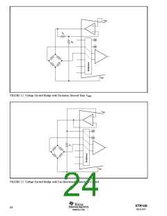
BRIDGE SENSOR CONNECTIONS
Fixed Voltage Excitation
There exists a class of sensors that are best supplied with a
voltage source excitation such as the bridge sensor shown in
Figure 12. The excitation voltage here is given by:
Three-Wire Connection
It is possible to minimize the errors caused by the lead-wire
resistance by connecting the RTD, see Figure 10. Operating
under the assumption that the wire connecting pin 1 to the
XTR108 is the same length as the wire at pin 2, and with the
current through the RTD identical to the current through RZ
any error voltage caused by the lead-wire is the same on both
sides. This appears as a common-mode voltage and is
subtracted by the PGA.
R1
VEX = VREF 1+
R2
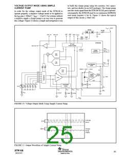
Uni-Directional Linearity Control
The circuit in Figure 13 shows a bridge sensor with an
excitation voltage that is adjusted to linearize the response
using the same algorithm as the RTD linearization.
The circuit in Figure 10 also shows a scheme where one
board can be optimized for a wide range of temperatures.
Consider a range of applications where there are up to five
different minimum temperatures. Select RZ1 through RZ5 to
be optimum for each of the minimum temperatures. The
configuration codes in the EEPROM can be set to select that
resistor for that unique situation.
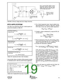
VEX = 2 • IREF RI
1kΩ
1
1kΩ
RLINE1
RTD
RZ
0.01µF
0.01µF
RLINE2
IRET
RCM
2
0.01µF
FIGURE 9. Two-Wire RTD Connection with RF Filter at Input Terminals.
XTR108
22
SBOS187C
www.ti.com

 BB [ BURR-BROWN CORPORATION ]