Hi-Z
SCLK
t8
t8
DIO
0
0
0
0
0
0
1
1
0
0
0
0
0
1
0
0
t9
Instruction/Address to EEPROM
Data from EEPROM
CS2
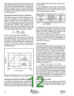
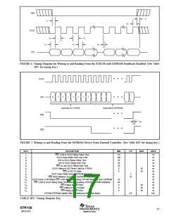
FIGURE 4. Timing Diagram for the XTR108 Continuous Readback Cycle. (See Table XIV for timing key.)
SCLK
t10
t11
DIO
t13
CS2
t12
CS1
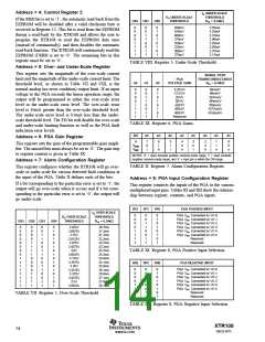
FIGURE 5. Interrupting an XTR108 EEPROM Readback Cycle. (See Table XIV for timing key.)
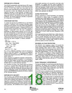
As long as CS1 is held LOW, the external system can write to
the EEPROM. See Figure 7 for this timing. Releasing CS1
will allow the XTR108 to resume in the read-back mode.
contents which will overwrite the data just loaded. Figure 6
shows read and write timing.
To be compatible with SPI EEPROM devices, the XTR108
latches input data on the rising edge of SCLK. Output data
transitions on the falling edge of SCLK. All serial interface
transactions must be framed by CS1. CS1 must be asserted
to start an operation, and it must be de-asserted to terminate
an operation.
For interactive calibration operations, the first command to
the XTR108 should set bit 0, Register 4 (RBD). This will
disable the read-back mode. It will be possible to write to the
various registers and cycle CS1. If RBD is not set, then as
soon as CS1 is released, the XTR108 will read the EEPROM
XTR108
16
SBOS187C
www.ti.com

 BB [ BURR-BROWN CORPORATION ]