TSC2005
www.ti.com
SBAS379–DECEMBER 2006
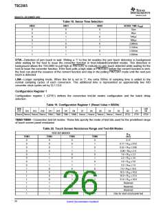
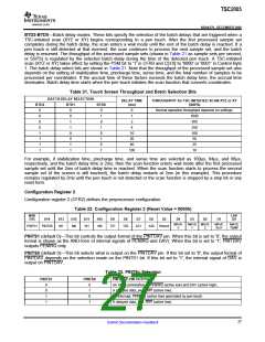
BTD2-BTD0—Batch delay modes. These bits specify the selection of the batch delays that are triggered when a
TSC-initiated scan (XYZ or XY) begins corresponding to a pen touch. After the first processed sample set
completes during the batch delay, the scan enters a wait mode until the end of the batch delay is reached. If a
pen touch is still detected at that moment, the scan continues to process the next sample set, and the batch
delay is resumed. The throughput of the processed sample sets (shown in Table 21 as sample sets per second,
or SSPS) is regulated by the selected batch delay during the time of the detected pen touch. A TSC-initiated
scan (XYZ or XY) takes effect by setting the PSM bit to '1' in CFR0 and C[3:0] to '0000' or '0001' in Control Byte
1. The batch delay select bits are shown in Table 21. Note that the throughput of the processed sample set also
depends on the setting of stabilization time, precharge time, sense time, and the total number of samples to be
processed per coordinates. If the accrual time of these factors exceeds the batch delay time, the accrual time
dominates. Batch delay time starts when the pen touch initiates the scan function that converts coordinates.
Table 21. Touch Screen Throughput and Batch Selection Bits
BATCH DELAY SELECTION
DELAY TIME
(ms)
THROUGHPUT for TSC-INITIATED SCAN XYZ or XY
(SSPS)
BTD2
BTD1
BTD0
0
0
0
0
1
1
1
1
0
0
1
1
0
0
1
1
0
1
0
1
0
1
0
1
0
1
Normal operation throughput depends on settings.
1000
500
250
100
50
2
4
10
20
40
100
25
10
For example, if stabilization time, precharge time, and sense time are selected as 100µs, 84µs, and 96µs,
respectively, and the batch delay time is 2ms, then the scan function enters wait mode after the first processed
sample set until the 2ms of batch delay time is reached. When the scan function starts to process the second
sample set (if the screen is still touched), the batch delay restarts at 2ms (in this example). This procedure
remains regulated by 2ms until the pen touch is not detected or the scan function is stopped by a stop bit or any
reset form.
Configuration Register 2
Configuration register 2 (CFR2) defines the preprocessor configuration.
Table 22. Configuration Register 2 (Reset Value = 0000h)
MSB
D15
LSB
D0
D14
D13
D12
D11
D10
D9
D8
D7
D6
D5
D4
D3
D2
D1
MAVE
X
MAVE MAVE
MAVE
AUX
MAVE
TEMP
PINTS1 PINTS0
M1
M0
W1
W0
TZ1
TZ0
AZ1
AZ0
Resrvd
Y
Z
PINTS1 (default 0)—This bit controls the output format of the PINTDAV pin. When this bit is set to '0', the output
format is shown as the AND-form of internal signals of PENIRQ and DAV). When this bit is set to '1', PINTDAV
outputs PENIRQ only.
PINTS0 (default 0)—This bit selects what is output on the PINTDAV pin. If this bit set to '0', the output format of
PINTDAV depends on the selection made on the PINTS1 bit. If this bit set to '1', the internal signal of DAV is
output on PINTDAV.
Table 23. PINTSx Selection
PINTS1
PINTS0
PINTDAV PIN OUTPUT =
0
0
1
1
0
1
0
1
An AND combination of PENIRQ (active low) and DAV (active high).
A delayed data_ava, DAV (active low).
An interrupt, PENIRQ (active low) generated by pen-touch.
A delayed data_ava, DAV (active low).
27
Submit Documentation Feedback

 BB [ BURR-BROWN CORPORATION ]