TSC2005
www.ti.com
SBAS379–DECEMBER 2006
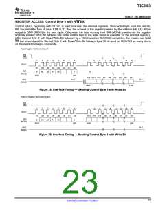
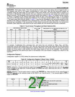
REGISTER ACCESS (Control Byte 0 with R/W Bit)
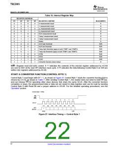
Control byte 0, beginning with D7 = 0, is used to access the internal registers. This control byte uses the last bit,
D0, to control the flow of data. If D0 is '1', then the content of the register pointed by the address bits (A3-A0) is
output to SDO (MISO) in the next cycle. Otherwise, the data coming from SDI (MOSI) is written to the register
properly pointed to by the address bits in the control byte (if the write mode is available for the pointed register).
After Control Byte 0 with Read/Write Bit followed by a 16-bit word on SDO/SDI completes, the master can hold
CS low to send another Control Byte 0 with Read/Write Bit followed by a 16-bit word on SDO/SDI as many times
as the master manages to operate.
Read Register Via Control Byte 0
CS
(SS)
1
2
3
4
5
6
7
8
1
2
3
7
8
11
15
16
SCLK
D7
D6
A3
D5
A2
D4
A1
D3
A0
D2
D1
D0
SDI
0
1
0
(MOSI)
MSB
LSB
D15 D14 D13 D9
D8
D5
D4
D1
D0
SDO
Hi-Z
Hi-Z
(MISO)
MSB
LSB
Figure 28. Interface Timing — Sending Control Byte 0 with Read Bit
Write to Register Via Control Byte 0
CS
(SS)
1
2
3
4
5
6
7
8
1
2
3
7
8
11
12
15
16
SCLK
D15 D14 D13 D9
D8
D5
D4
D1
D0
D7
D6
A3
D5
A2
D4
A1
D3
A0
D2
D1
D0
SDI
0
0
(MOSI)
MSB
LSB
MSB
LSB
SDO
Hi-Z
(MISO)
Figure 29. Interface Timing — Sending Control Byte 0 with Write Bit
23
Submit Documentation Feedback

 BB [ BURR-BROWN CORPORATION ]