TSC2005
www.ti.com
SBAS379–DECEMBER 2006
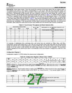
M1, M0, W1, W0 (default 0000)—Preprocessing MAV filter control. Note that when the MAV filter is processing
data, the STS bit and the corresponding DAV bits in the status register will indicate that the converter is busy
until all conversions necessary for the preprocessing are complete. The default state for these bits is 0000,
which bypasses the preprocessor. These bits are the same whether reading or writing.
TZ1 and TZ0, or AZ1 and AZ0 (default 00)—Zone detection bit definition (for TEMP or AUX measurements).
TZ1 and TZ0 are for the TEMP measurement. AZ1 and AZ0 are for the AUX measurement. The action taken in
zone detection is to store the processed data in the corresponding data registers and to update the
corresponding DAV bits in status register. If the processed data do not meet the selected criteria, these data are
ignored and the corresponding DAV bits are not updated. When zone detection is disabled, the processed data
are simply stored in the corresponding data registers and the corresponding DAV bits are updated without any
comparison of criteria. Note that the converted samples are always processed according to the setting of the
MAVE bits for AUX/TEMP before zone detection takes effect. SeeTable 30 for thresholds.
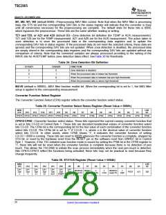
Table 24. Zone Detection Bit Definition
TZ1/AZ1
TZ0/AZ0
FUNCTION
0
0
1
1
0
1
0
1
Zone detection is disabled.
When the processed data is below low threshold
When the processed data is between low and high thresholds
When the processed data is above high threshold
MAVE (default is 00000)—MAV filter function enable bit. When the corresponding bit is set to 1, the MAV filter
setup is applied to the corresponding measurement.
Converter Function Select Register
The Converter Function Select (CFN) register reflects the converter function select status.
Table 25. Converter Function Select Status Register (Reset Value = 0000h)
MSB
D15
LSB
D0
D14
D13
D12
D11
D10
D9
D8
D7
D6
D5
D4
D3
D2
D1
CFN15 CFN14 CFN13 CFN12 CFN11 CFN10 CFN9
CFN8
CFN7
CFN6
CFN5
CFN4
CFN3
CFN2
CFN1
CFN0
CFN15-CFN0—Converter function select status. These bits represent the current running converter function that
is set in bits C3-C0 of Control Byte 1. These bits are decoded hexidecimal values of converter function select
bits C3-C0. The CFNx bit is the corresponding bit for the hex value of each combination of the converter function
select bits C3-C0. The CFNx bit is set to '1' if C3-C0 = x, where x is the decimal value of converter function
select bits C3-C0. In other words, when CFN0 shows '1', it indicates the converter function of setting
C3-C0 = 0000 is running. These bits are reset to 0000h whenever the converter function is complete, stopped by
STS bit, or reset by the hardware reset from the RESET pin or the software reset from SWRST bit in Control
Byte 1. However, if the TSC-initiated scan function mode is issued by setting the PSM bit in the CFR0 register to
'1', these bits will not be reset when the converter function is complete because there is no detection of pen
touch. This allows the TSC2005 to initiate the scan process immediately when the next pen touch is detected.
Bits CFN15-CFN13 reflect the functions being activated; these bits may not be practical to read because they
change frequently.
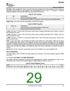
Table 26. STATUS Register (Reset Value = 0004h)
MSB
D15
LSB
D0
D14
D13
D12
D11
D10
D9
D8
D7
D6
D5
D4
D3
D2
D1
DAV
Due
X
DAV
Due
Y
DAV
Due
Z1
DAV
Due
Z2
DAV
Due
AUX
DAV
Due
TEMP1 TEMP2
DAV
Due
RESRVD RESET
(read '0') Flag
X
CON
Y
CON
RESRVD
(read '0')
Y
SHR
PDST
ID1
ID0
28
Submit Documentation Feedback

 BB [ BURR-BROWN CORPORATION ]