TSC2005
www.ti.com
SBAS379–DECEMBER 2006
COMMUNICATION PROTOCOL
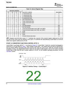
The TSC2005 is controlled entirely by registers. Reading and writing to these registers are accomplished by the
use of Control Byte 0, which includes a 4-bit address plus one read/write control bit. The data registers defined
in Table 10 are all 16-bit, right-adjusted. NOTE: Except for some configuration registers and the Status register
that are full 16-bit registers, the rest of the value registers are 12-bit (or 10-bit) data preceded by four (or six)
zeros.
Configuration Register 0
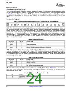
Table 11. Configuration Register 0 (Reset Value = 4000h for Read; 0000h for Write)
MSB
D15
LSB
D0
D14
D13
D12
D11
D10
D9
D8
D7
D6
D5
D4
D3
D2
D1
PSM
STS
RM
CL1
CL0
PV2
PV1
PV0
PR2
PR1
PR0
SN2
SN1
SN0
DTW
LSM
PSM—Pen status/control mode. Reading this bit allows the host to determine if the screen is touched. Writing to
this bit selects the mode used to control the flow of converter functions that are either initiated and/or controlled
by host or under control of the TSC2005 responding to a pen touch. When reading, the PSM bit indicates if the
pen is down or not. When writing to this register, this bit determines if the TSC2005 controls the converter
functions, or if the converter functions are host-controlled. The default state is the host-controlled converter
function mode (0). The other state (1) is the TSC-initiated scan function mode that must only collaborate with
C3-C0 = 0000 or 0001 in order to allow the TSC2005 to initiate and control the scan function for XYZ or XY
when a pen touch is detected.
Table 12. PSM Bit Operation
OPERATION
Read
VALUE
DESCRIPTION
0
1
0
1
No screen touch detected
Read
Screen touch detected
Write
Converter functions initiated and/or controlled by host
Converter functions initiated and controlled by the TSC2005
Write
STS—A/D converter status. When reading, this bit indicates if the converter is busy or not busy. Continuous
scans or conversions can be stopped by writing a '1' to this bit, immediately halting the running converter
function (even if the pen is still down) and causing the A/D converter to power down. The default state for write
is 0 (normal operation), and the default state for read is 1 (converter is not busy). NOTE: The same bit can be
written through Control Byte 1.
Table 13. STS Bit Operation
OPERATION
Read
VALUE
DESCRIPTION
0
1
0
1
Converter is busy
Read
Converter is not busy
Normal operation
Write
Write
Stop converter function and power down
RM—Resolution control. The A/D converter resolution is specified with this bit. See Table 14 for a description of
these bits. This bit is the same whether reading or writing, and defaults to 0. Note that the same bit can be
written through Control Byte 1.
Table 14. A/D Converter Resolution Control
RM
0
FUNCTION
10-bit resolution. Power-up and reset default.
12-bit resolution
1
24
Submit Documentation Feedback

 BB [ BURR-BROWN CORPORATION ]