TSC2005
www.ti.com
SBAS379–DECEMBER 2006
OPERATION
TOUCH SCREEN MEASUREMENTS
As noted previously in the discussion of the A/D converter, several operating modes can be used that allow
great flexibility for the host processor. This section examines these different modes.
Conversion Controlled by TSC2005 Initiated by TSC2005 (TSMode 1)
In TSMode 1, before a pen touch can be detected, the TSC2005 must be programmed with PSM = 1 and one of
two scan modes:
1. X-Y-Z Scan (converter function select bits C[3:0] = Control Byte 1 D[6:3] = 0000); or
2. X-Y Scan (converter function select bits C[3:0] = Control Byte 1 D[6:3] = 0001).
See Table 7 for more information on the converter function select bits.
When the touch panel is touched, which causes the internal pen-touch signal to activate, this lowers the
PINTDAV output if it is programmed as PENIRQ. The TSC2005 will then execute the preprogrammed scan
function without a host intervention.
At the same time, the TSC2005 starts up its internal clock. It then turns on the Y-drivers, and after a
programmed panel voltage stabilization time, powers up the A/D converter and converts the Y coordinate. If
preprocessing is selected, several conversions may take place. When data preprocessing is complete, the Y
coordinate result is stored in a temporary register.
If the screen is still touched at this time, the X-drivers are enabled, and the process repeats, but measuring the
X coordinate instead, and storing the result in a temporary register.
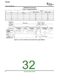
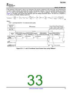
If only X and Y coordinates are to be measured, then the conversion process is complete. A set of X and Y
coordinates are stored in the X and Y registers. Figure 31 shows a flowchart for this process. The time it takes
to go through this process depends upon the selected resolution, internal conversion clock rate, panel voltage
stabilization time, precharge and sense times, and whether preprocessing is selected. The time needed to get a
complete X and Y coordinate (sample set) reading can be calculated by:
f
LPPRO
fOSC
OHDLY1
fOSC
OH1
fOSC
1
fOSC
OSC )OHCONV
fADC
@
)
)2 @ ǒ
Ǔ)2 @ N @ ǒB)2 @
(
)
Ǔ ǒ Ǔ ǒ Ǔ
ǒ
Ǔ
tCOORDINATE
+
tPVS)tPRE)tSNS
)
(5)
Where:
tCOORDINATE = time to complete X/Y coordinate reading.
tPVS = panel voltage stabilization time, as given in Table 16.
tPRE = precharge time, as given in Table 17.
tSNS = sense time, as given in Table 18.
N = number of measurements for MAV filter input, as given in Table 3 as N.
(For no MAV: M1-0[1:0] = '00', W1-0[1:0] = '00', N = 1.)
B = number of bits of resolution.
fOSC = TSC onboard OSC clock frequency. See Electrical Characteristics for supply frequency (SNSVDD).
fADC = A/D converter clock frequency, as given in Table 15.
OH1 = overhead time #1 = 2.5 internal clock cycles.
OHDLY1 = total overhead time for tPVS, tPRE, and tSNS = 10 internal clock cycles.
OHCONV = total overhead time for A/D conversion = 3 internal clock cycles.
LPPRO = pre-processor preocessing time as given in Table 31.
31
Submit Documentation Feedback

 BB [ BURR-BROWN CORPORATION ]