PCM1804
SLES022A – DECEMBER 2001
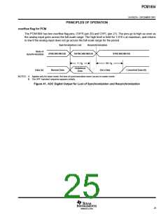
PRINCIPLES OF OPERATION
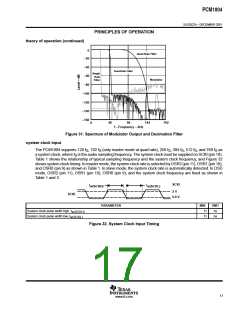
data format
The PCM1804 supports four audio data formats in both of master and slave mode, and these data formats are
selected by the FMT0 (pin 6) and FMT1 (pin 7) as shown in Table 5.
Table 5. Data Format
FMT1
Low
FMT0
Low
FORMAT
MASTER
Yes
SLAVE
Yes
PCM, Left justified, 24 bit.
2
Low
High
Low
PCM, I S, 24 bit.
Yes
Yes
High
High
PCM, Standard, 24 bit
DSD
Yes
Yes
High
Yes
—
interface timing for PCM
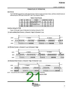
Figure 36 through Figure 38 illustrate the interface timing for PCM.
(1) Left-Justified Data Format; L-Channel = High, R-Channel = Low
1/f
S
LRCK
L-Channel
R-Channel
BCK
DATA
1
2
3
22 23 24
1
2
3
22 23 24
1 2
2
(2) I S Data Format; L-Channel = Low, R-Channel = High
1/f
S
L-Channel
R-Channel
LRCK
BCK
1
2
3
22 23 24
1
2
3
22 23 24
1 2
DATA
(3) Standard Data Format; L-Channel = High, R-Channel = Low
1/f
S
L-Channel
R-Channel
LRCK
BCK
22 23 24
1
2
3
22 23 24
1
2
3
22 23 24
DATA
NOTE: LRCK and BCK work as outputs at master mode, inputs at slave mode, respectively.
Figure 36. Audio Data Format for PCM
21
www.ti.com

 BB [ BURR-BROWN CORPORATION ]