PCM1804
SLES022A – DECEMBER 2001
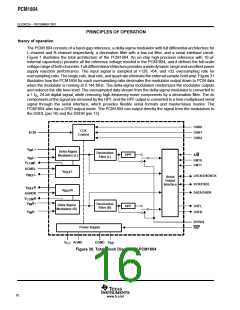
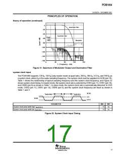
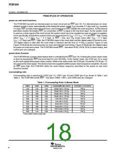
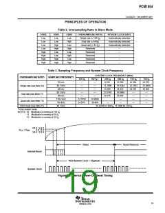
PRINCIPLES OF OPERATION
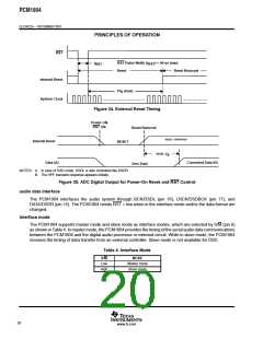
RST
RST Pulse Width (t ) = 40 ns (min)
RST
t
RST
Reset
Reset Removal
Internal Reset
System Clock
1/f (max)
S
Figure 34. External Reset Timing
Power ON
RST ON
Reset Removal
READY / OPERATION
Internal Reset
RESET
1116 / f
S
Data (A)
Converted Data (B)
Zero Data
NOTES: A. In case of DSD mode, DSDL is also controlled like DSDR.
B. The HPF transient response appears initially.
Figure 35. ADC Digital Output for Power-On Reset and RST Control
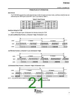
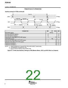
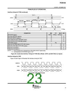
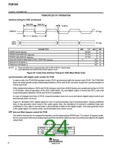
audio data interface
The PCM1804 interfaces the audio system through BCK/DSDL (pin 16), LRCK/DSDBCK (pin 17), and
DATA/DSDR (pin 15). The PCM1804 needs RST = low when in the interface mode and/or the data format are
changed.
interface mode
The PCM1804 supports master mode and slave mode as interface modes, which are selected by S/M (pin 8)
as shown in Table 4. In master mode, the PCM1804 provides the timing of the serial audio data communications
between the PCM1804 and the digital audio processor or external circuit. While in slave mode, the PCM1804
receives the timing of data transfer from an external controller. Slave mode is not available for DSD.
Table 4. Interface Mode
S/M
Low
High
MODE
Master mode
Slave mode
20
www.ti.com

 BB [ BURR-BROWN CORPORATION ]