PCM1804
SLES022A – DECEMBER 2001
PRINCIPLES OF OPERATION
overflow flag for PCM
The PCM1804 has two overflow flag pins, OVFR (pin 20) and OVFL (pin 21). The pins go to high as soon as
the analog input goes across the full-scale range. The high level is held for 1.016 s at maximum, and returns
to low if the analog input does not go across the full-scale range for the period.
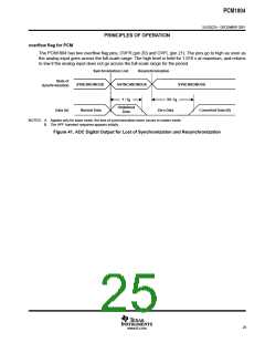
Synchronization Lost
Resynchronization
State of
Synchronization
SYNCHRONOUS
ASYNCHRONOUS
SYNCHRONOUS
1 / f
90 / f
S
S
Undefined
Data
Data (A)
Normal Data
Zero Data
Converted Data (B)
NOTES: A. Applies only for slave mode, the loss of synchronization never occurs in master mode.
B. The HPF transient response appears initially.
Figure 41. ADC Digital Output for Lost of Synchronization and Resynchronization
25
www.ti.com

 BB [ BURR-BROWN CORPORATION ]