PCM1804
SLES022A – DECEMBER 2001
PRINCIPLES OF OPERATION
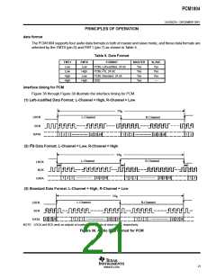
theory of operation (continued)
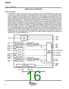
0
Quad-Rate Filter
–20
–40
–60
–80
Dual-Rate Filter
Single
Rate
Filter
Modulator
–100
–120
–140
–160
48
96
144
192
0
f – Frequency – kHz
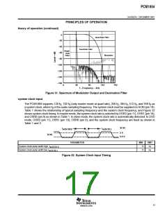
Figure 31. Spectrum of Modulator Output and Decimation Filter
system clock input
The PCM1804 supports 128 f , 192 f (only master mode at quad rate), 256 f , 384 f , 512 f , and 768 f as
S
S
S
S
S
S
a system clock, where f is the audio sampling frequency. The system clock must be supplied on SCKI (pin 18).
S
Table 1 shows the relationship of typical sampling frequency and the system clock frequency, and Figure 32
shows system clock timing. In master mode, the system clock rate is selected by OSR2 (pin 11), OSR1 (pin 10),
and OSR0 (pin 9) as shown in Table 1. In slave mode, the system clock rate is automatically detected. In DSD
mode, OSR2 (pin 11), OSR1 (pin 10), OSR0 (pin 9), and the system clock frequency are fixed as shown in
Table 1 and 3.
SCKI
t
t
w(SCKL)
w(SCKH)
2 V
SCKI
0.8 V
PARAMETER
MIN
11
11
UNIT
ns
System clock pulse width high, t
w(SCKH)
System clock pulse width low, t
ns
w(SCKL)
Figure 32. System Clock Input Timing
17
www.ti.com

 BB [ BURR-BROWN CORPORATION ]