User-Configuration of the HCPL-316J Input Side
HCPL-316J
The V , V , FAULT and RESET input pins make a wide
1
2
3
4
5
6
7
8
V
V
V
IN+ IN-
IN+
IN-
variety of gate control and fault configurations possible,
depending on the motor drive requirements. The HC-
PL-316J has both inverting and noninverting gate con-
trol inputs, an open collector fault output suitable for
wired ‘OR’applications and an active low reset input.
CC1
+
–
µC
GND1
RESET
FAULT
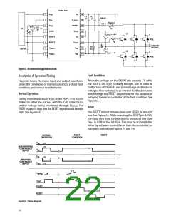
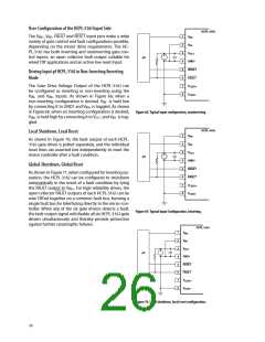
Driving Input pf HCPL-316J in Non-Inverting/Inverting
Mode
V
The Gate Drive Voltage Output of the HCPL-316J can
be configured as inverting or non-inverting using the
LED1+
V
LED1-
V
and V
inputs. As shown in Figure 68, when a
IN–
IN+
non-inverting configuration is desired, V is held low
IN–
by connecting it to GND1 and V is toggled. As shown
IN+
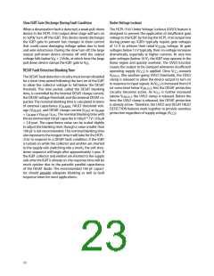
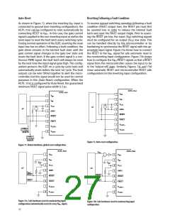
in Figure69, when an inverting configuration is desired,
Figure 68. Typical input configuration, noninverting.
V
is held high by connecting it to V and V is tog-
CC1 IN–
IN+
gled.
HCPL-316J
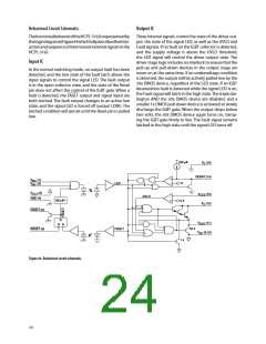
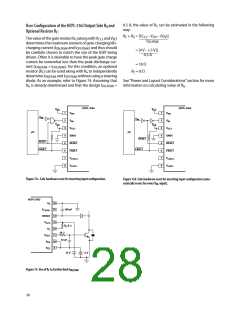
Local Shutdown, Local Reset
1
2
3
4
5
6
7
8
V
V
V
IN+
IN-
As shown in Figure 70, the fault output of each HCPL-
316J gate driver is polled separately, and the individual
reset lines are asserted low independently to reset the
motor controller after a fault condition.
CC1
+
–
µC
GND1
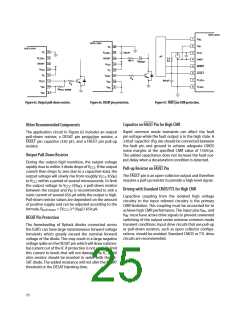
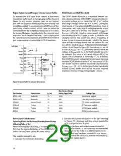
Global-Shutdown, Global Reset
RESET
FAULT
As shown in Figure 71, when configured for inverting op-
eration, the HCPL-316J can be configured to shutdown
automatically in the event of a fault condition by tying
V
V
LED1+
LED1-
the FAULT output to V . For high reliability drives, the
IN+
open collector FAULT outputs of each HCPL-316J can be
wire ‘OR’ed together on a common fault bus, forming a
single fault bus for interfacing directly to the micro-con-
troller. When any of the six gate drivers detects a fault,
the fault output signal will disable all six HCPL-316J gate
drivers simultaneously and thereby provide protection
against further catastrophic failures.
Figure 69. Typical Input Configuration, Inverting.
HCPL-316J
1
2
3
4
5
6
7
8
V
V
V
IN+
IN-
CC1
+
–
µC
GND1
RESET
FAULT
V
V
LED1+
LED1-
Figure 70. Local shutdown, local reset configuration.
26

 AVAGO [ AVAGO TECHNOLOGIES LIMITED ]