Arria GX Architecture
f
For more information about differential on-chip termination, refer to the
High-Speed Differential I/O Interfaces with DPA in Arria GX Devices chapter
in volume 2 of the Arria GX Device Handbook.
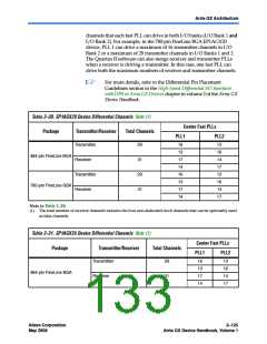
For more information about tolerance specifications for differential
on-chip termination, refer to the DC & Switching Characteristics chapter in
volume 1 of the Arria GX Device Handbook.
On-Chip Series Termination
Arria GX devices support driver impedance matching to provide the I/O
driver with controlled output impedance that closely matches the
impedance of the transmission line. As a result, reflections can be
significantly reduced. Arria GX devices support on-chip series
termination for single-ended I/O standards with typical RS values of 25
and 50 Ω. Once matching impedance is selected, current drive strength is
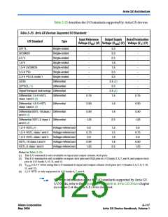
no longer selectable. Table 2–26 shows the list of output standards that
support on-chip series termination.
f
f
For more information about series on-chip termination supported by
Arria GX devices, refer to the Selectable I/O Standards in Arria GX Devices
chapter in volume 2 of the Arria GX Device Handbook.
For more information about tolerance specifications for on-chip
termination without calibration, refer to the DC & Switching
Characteristics chapter in volume 1 of the Arria GX Device Handbook.
MultiVolt I/O Interface
The Arria GX architecture supports the MultiVolt I/O interface feature
that allows Arria GX devices in all packages to interface with systems of
different supply voltages. Arria GX VCCINTpins must always be
connected to a 1.2-V power supply. With a 1.2-V VCCINT level, input pins
are 1.2-, 1.5-, 1.8-, 2.5-, and 3.3-V tolerant. The VCCIOpins can be
connected to either a 1.2-, 1.5-, 1.8-, 2.5-, or 3.3-V power supply,
depending on the output requirements. The output levels are compatible
with systems of the same voltage as the power supply (for example, when
VCCIOpins are connected to a 1.5-V power supply, the output levels are
compatible with 1.5-V systems). Arria GX VCCPDpower pins must be
connected to a 3.3-V power supply. These power pins are used to supply
the pre-driver power to the output buffers, which increases the
performance of the output pins. The VCCPDpins also power
configuration input pins and JTAG input pins.
Altera Corporation
May 2008
2–121
Arria GX Device Handbook, Volume 1

 ALTERA [ ALTERA CORPORATION ]