[AK4679]
■ MIC Input Recording (Stereo)
Example:
PLL Master Mode
Audio I/F Format: MSB justified (ADC & DAC)
Sampling Frequency: 44.1kHz
Pre MIC AMP: +15dB
MIC Power 1: 2.5V Output
ALC setting: Refer to Table 34
ALC: Enable
FS3-0 bits
0000
1111
AAH
(Addr:03H, D7-4)
(1)
MIC Control
55H
(1) Addr:04H, Data:FxH
(2) Addr:07H, Data: AAH
(3) Addr:06H, Data: xxH
(Addr:07H, D7-0)
(2)
MIC Signal Select
00H
xxH
xxH
xxH
(Addr:06H)
(3)
ALC Setting
(Addr:13H, 15H, 16H)
(4)
(4) Addr:13H, 15H, 16H, Data:xxH
ALC Enable
(Addr:17H)
02H
03H
02H
(5)
(10)
(5) Addr:17H, Data:03H
(6) Addr:02H, Data:01H
(7) Addr:00H, Data:33H
ALC State
ALC Disable
ALC Disable
ALC Enable
(6)
(9)
PMMP1 bit
(Addr:02H, D0)
(7)
(8)
PMADL/R bits
PMPFILbit
(Addr:00H, D5-4, D1)
Recording
1059/fs
(8) Addr:00H, Data:01H
ADC Output
Data
Initialize Normal State
"L" Output
"L" Output
(9) Addr:02H, Data:00H
(10) Addr:17H, Data:02H
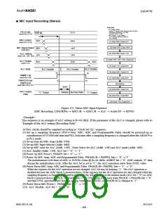
Figure 153. Stereo MIC Input Sequence
(MIC Recording: LINx/RINx → MICL/R → ADCL/R → ALC → Audio I/F → SDTO)
<Example>
This sequence is an example of ALC setting at fs=44.1kHz. If the parameter of the ALC is changed, please refer to
“Example of the ALC setting (Recording Path)”.
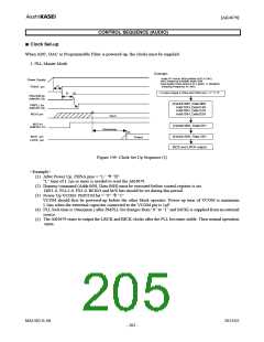
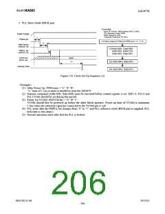
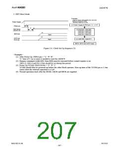
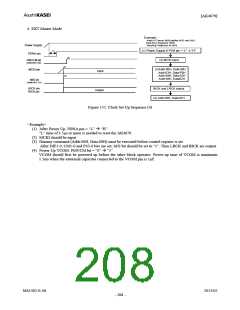
At first, clocks should be supplied according to “Clock Set Up” sequence.
(1) Set up a sampling frequency (FS3-0 bits). MIC, ADC and Programmable Filter should be powered-up in
consideration of VCOM ride time and PLL lock time after a sampling frequency is changed when the AK4679 is
in PLL mode.
(2) Set up Gain for MIC-Amp (Addr: 07H)
(3) Set up MIC Input Selector (Addr: 06H)
(4) Set up REF value for ALC (Addr: 13H) , Timer Select for ALC (Addr: 15H) and ALC mode (Addr: 16H)
(5) ALC Enable (Addr: 17H): ALC bit = “0” → “1”
(6) Power Up MIC Power1: PMMP1 bit = “0” → “1”
(7) Power Up MIC-Amp, ADC and Programmable Filter: PMADL/R = PMPFIL bits = “0”→“1”
The initialization cycle time of ADC is 1059/fs=24ms @ fs=44.1kHz, ADRST bit = “0”. ADC outputs “0” data
during the initialization cycle. After the ALC bit is set to “1”, the ALC operation starts from IVOL value
(8) Power Down MIC-Amp, ADC and Programmable Filter: PMADL/R= PMPFIL bits = “1” → “0”
When the registers for the ALC operation are not changed, ALC bit may be keeping “1”. The ALC operation is
disabled because the ADC block is powered-down. If the registers for the ALC operation are also changed when the
sampling frequency is changed, it should be done after the AK4679 goes to the manual mode (ALC bit = “0”) or ADC
block is powered-down (PMADL = PMADR bits = “0”). IVOL gain is not reset when PMADL = PMADR bits = “0”,
and then IVOL operation starts from the setting value when PMADL or PMADR bit is changed to “1”.
(9) Power Down MIC Power 1: PMMP1 bit = “1” → “0”
(10) ALC Disable: ALC bit = “1” → “0”
MS1402-E-06
2013/02
- 209 -

 AKM [ ASAHI KASEI MICROSYSTEMS ]