HDMP-1022 (Tx), HDMP-1024 (Rx)
Operating Modes
M20SEL
FLAGSEL
Description
0
0
1
1
0
1
0
1
16 bit data plus error checking
16 bit data plus FLAG
20 bit data plus error checking
20 bit data plus FLAG
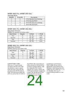
HDMP-1022 (Tx), HDMP-1024 (Rx)
Data Frame Structure
M20SEL Not Asserted (16 bit data mode)
Data Status
True
Flag bit
D-Field
D0 - D15
D0 - D15
D0 - D15
D0 - D15
C-Field
1101
0
0
1
1
Inverted
True
0010
1011
Inverted
0100
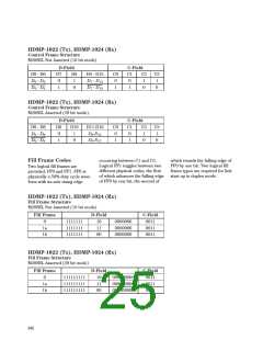
HDMP-1022 (Tx), HDMP-1024 (Rx)
Data Frame Structure
M20SEL Asserted (20 bit data mode)
Data Status
True
Flag bit
D-Field
D0 - D19
D0 - D19
D0 - D19
D0 - D19
C-Field
1101
0
0
1
1
Inverted
True
0010
1011
Inverted
0100
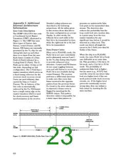
Control Frame Codes
the D-Field. The control frame is
either inverted or not inverted as
needed to maintain balance, with
the coding bits 0011 used to
complement control frames.
There are 218 control words
These middle bits are used to
distinguish control frames from
fill frames, which always have the
middle bits set to either 00, 11, or
provided in 20 bit mode. If the
user desires to send a control
word, his lower 9 bits (D0-D8)
are sent as bits D0-D8 of the D-
Field. The user’s next 9 bits (D9-
D17) are sent as bits D11-D19 of
indicate true control, and the bits
1100 used to indicate complement 10. Similarly, there are 214
control. The bits d9 and d10 are
always forced to 0 1 for true
control frames and 1 0 for
control words provided in 16 bit
mode.
639

 AGILENT [ AGILENT TECHNOLOGIES, LTD. ]