Appendix I: Additional
Internal Architecture
Information
Detailed coding schemes are
described in the following
generate an undetectable false
lock point in the transmitted data
stream. The detection also
reduces the probability that the
loop could lock onto random data
at a point away from the true
master transition for any
significant time before it would be
detected as a false lock. This
mode can detect all single-bit
errors in the C-field (non-data bit
fields) of the frame.
subsections. All the tables given
in this section show data bits in
the same configuration as a scope
display. In other words, the
leftmost bit in each table is the
first bit to be transmitted in time,
while the rightmost bit is the last
bit to be transmitted.
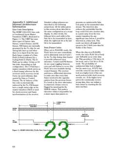
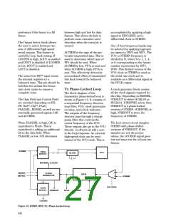
Line Code Description
The HDMP-1022/1024 line code
is Conditional Invert Master
Transition (CIMT), illustrated in
Figure 11. The CIMT line uses
three types of frames: data
frames, control frames, and fill
frames. Fill frames are internally
generated by the Tx chip for use
during link start up and when
there is no input from the user.
Each frame consists of a Data
Field (D-Field) followed by a
Coding Field (C-Field). The D-
Field can be either 16-bits or 20-
bits wide, depending on link
configuration. The C-Field has a
master transition which serves as
a fixed timing reference for the
receivers clock recovery circuit.
Users can send arbitrary data
carried by Data or Control
Data Frame Codes
When not in FLAGSEL mode, the
FLAG bit is not user controllable
and is alternately sent as 0 and 1
by the Tx chip during data frames
to provide enhanced error
detection. Control and Fill frames
do not cause toggling between
even and odd frames to occur (the
FLAG bit is not available during
control frames). The receiver
performs a differential detection
to make sure that every data
frame received is the opposite
pattern from the previous frame.
If a break in the strict alternation
is observed, a frame error is
flagged by asserting the Rx
When the chip is in FLAGSEL
mode, the extra FLAG bit is freely
user definable as an extra data
bit. This provides a 17th bit in 16
bit mode, and a 21st bit in 20 bit
mode. The probability of
undetected false lock is higher,
but the users (e.g., SCI-FI) that
need the extra bit can detect false
lock at a higher level of the net-
work protocol with clock recovery
circuits, etc. If the higher level
protocols consistently receive
wrong data, they can initiate a
link restart by resetting the Rx
state machine.
Frames. The dc balance of the
line code is automatically
enforced by the Tx. Fill frames
have a single rising edge at the
master transition which is used
for clock recovery and frame
synchronization at the receiver.
ERROR output. This pattern
detection makes it impossible for
a static input data pattern to
CODING FIELD
4 BITS
DATA FIELD
16/20 BITS
SERIAL
DATA
MASTER
TRANSITION
FILL
FRAME
FRAME K
FRAME K+1
Figure 11. HDMP-1022/1024 (Tx/Rx Pair) Line Code.
638

 AGILENT [ AGILENT TECHNOLOGIES, LTD. ]