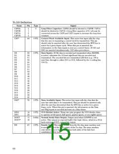
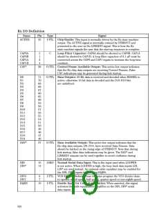
Rx I/O Definition
Name
Pin
Type
Signal
ACTIVE
25
I-TTL Chip Enable: This input is normally driven by the Rx state machine
output. The ACTIVE signal is internally retimed by STRBOUT and
presented to the user as the LINKRDY signal. This is how the Rx
state machine signals the user that the start-up sequence is complete.
CAP0A
CAP0B
CAP1A
CAP1B
2
1
3
4
C
Loop Filter Capacitor: CAP0A should be shorted to CAP0B. CAP1A
should be shorted to CAP1B. A loop filter capacitor of 0.1 µF must be
connected across the CAP0 and CAP1 inputs to increase the loop time
constant.
CAV*
38
O-TTL Control Frame Available Output: This active-low output indicates
that the Rx chip data outputs are receiving Control Frames. False
CAV indications may be generated during link startup.
D0
D1
D2
D3
D4
D5
D6
D7
71
70
69
68
67
66
65
60
59
58
57
56
55
54
51
50
49
48
47
46
O-TTL Data Outputs: 20 Bit data is received and decoded when M20SEL is
active; otherwise 16 bit data is decoded and the D16-D19 bits
are undefined.
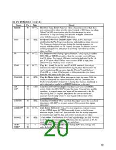
D8
D9
D10
D11
D12
D13
D14
D15
D16
D17
D18
D19
DAV*
37
O-TTL Data Available Output: This active-low output indicates that the
Rx chip data outputs, D0..D19, have received Data Frames. Data
should be latched on the rising edge of STRBOUT. Note that during
link startup, false data indications may be given. The DAV* and
LINKRDY outputs can be used together to avoid confusion during
link startup.
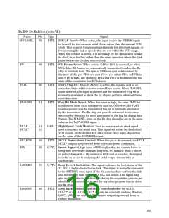
DIN
DIN*
15
14
I-H50 Normal Serial Data Input: This is the input used when LOOPEN
is not active. When LOOPEN is high, the loop back data inputs LIN,
LIN* are used instead. An optional cable equalizer may be enabled for
the DIN, DIN* inputs by asserting EQEN.
DIV0
DIV1
6
7
I-TTL VCO Divider Select: These two pins program the VCO divider chain
to operate at full speed, half speed, quarter speed or one-eighth speed.
EQEN
19
I-TTL Enable Input for Cable Equalization: When asserted, this signal
activates the cable equalization amplifier on the DIN, DIN* serial
data inputs.
634

 AGILENT [ AGILENT TECHNOLOGIES, LTD. ]