AD5940
Data Sheet
WAVEFORM GENERATOR
The AD5940 implements a digital waveform generator for
generating sinusoid, trapezoid, and square waveforms. This
section describes how to use the waveform generator.
The sinusoid generator includes a programmable phase offset
controlled by the WGOFFSET register. When enabled, the phase
accumulator is initialized with the contents of the phase offset
register. After the sinusoid generator starts, the phase increment
is always positive.
WAVEFORM GENERATOR FEATURES
The waveform generator features sine wave, trapezoid, and
square wave capabilities and can be used with the high speed
DAC or the low power DAC.
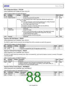
Trapezoid Generator
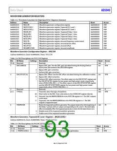
The definition of the trapezoid waveform is shown in Figure 43
SINE
GENERATION
DC LEVEL 2
DC LEVEL 1
TRAPEZOID
DAC
DELAY 1
TIME
SLOPE 1
TIME
DELAY 2
TIME
SLOPE 2 DELAY 1
GENERATION
TIME
TIME
SECOND
PERIOD
FIRST
PERIOD
Figure 43. Trapezoid Waveform Definition
DAC CODE
(DC)
The six parameters shown in Figure 43 are user programmable
through the WGDCLEVEL1, WGDCLEVEL2, WGDELAY1,
WGDELAY2, WDSLOPE1, and WGSLOPE2 registers. These
variables define the trapezoid waveform. By setting the
WGSLOPEx register to 0x00000, a square wave is generated.
The times are expressed in the number of periods of the DAC
update clock, which is set to 320 kHz for the trapezoid function.
A period of the trapezoid waveform begins at the start of
WGDELAY1 and completes at the end of WGSLOPE2. The
trapezoid continues to loop until it is disabled by the user.
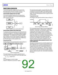
Figure 41. Simplified Waveform Generator Block Diagram
WAVEFORM GENERATOR OPERATION
To enable the waveform generator block, set the WAVEGENEN bit
in the AFECON register to 1. When this bit is enabled, the selected
waveform source starts and loops until either the block is disabled
(WAVEGENEN = 0), or another source is selected. When the
block is disabled, the DAC output maintains the voltage until a
different waveform is selected by writing to the TYPESEL bit in
the WGCON register, or if the waveform is reset.
USING THE WAVEFORM GENERATOR WITH THE
LOW POWER DAC
Sinusoid Generator
The block diagram for the sinusoid generator is shown in Figure 42.
Although the waveform generator is primarily designed for use
with the high speed DAC, it can also be used with the low power
DAC for ultra low power and low bandwidth applications. To
configure the low power DAC for generating waveforms, set
Bit 6 in the LPDACCON register to 1. Trapezoid or sinusoid
can be selected as described previously. The 32 kHz oscillator
must be selected as the system clock when using the waveform
generator with the low power DAC, which limits the bandwidth
of the signal.
PHASE
FREQUENCY CONTROL
WORD
AMPLITUDE
OFFSET
OFFSET
PHASE TO
AMPLITUDE
PHASE
ACCUMULATOR
DAC
CONVERSION
SINE
GENERATION
SCALING COMMON-MODE
ADJUSTMENT
Figure 42. Sinusoid Generator
The output frequency (fOUT) is adjusted using the frequency
control word (WGFCW, Bits[30:0]) with the following formula:
f
OUT = fACLK × SINEFCW/230
where:
ACLK is the frequency of ACLK, 16 MHz.
SINEFCW is Bits[30:0] in the WGFCW register.
f
Rev. 0 | Page 92 of 130

 ADI [ ADI ]