VS1005g Datasheet
10 VS1005 PERIPHERALS AND REGISTERS
10.21 10-Bit Analog-to-Digital Converter (ADC)
Vs1005 has a 10-bit ADC with following features:
• Successive Approximation Register conversion (SAR)
• Up to 5 analog input channels
• Up to 0.1Msps conversion speed
• AVDD voltage as reference
• Continuous or software enabled (once only) operation modes
• input range from 0V to AVDD
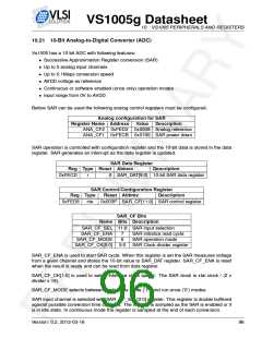
Before SAR can be used the following analog control registers must be configured.
Analog configuration for SAR
Register Name Address Value Description
ANA_CF2 0xFED2 0x0008 Analog reference
ANA_CF1 0xFECB 0x0100 SAR power down
SAR operation is controlled with configuration register and the 10-bit data is stored in the data
register. SAR generates an interrupt as the data register is updated.
SAR Data Register
Reg Type Reset Abbrev
Description
0xFECD SAR_DAT[9:0] 10-bit SAR data register
r
0
SAR Control/Configuration Register
Reg Type Reset Abbrev Description
0xFED6 r/w
0x003F SAR_CF[11:0] SAR control register
SAR_CF Bits
Name Bits Description
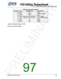
SAR_CF_SEL 11:8 SAR input selection
SAR_CF_ENA
SAR_CF_MODE
7
6
SAR initialize read cycle
SAR operation mode
SAR_CF_CK[5:0] 5:0 SAR Clock divider register
SAR_CF_ENA is used to start SAR cycle. When this register is set the SAR measures voltage
from a given channel and stores the 10-bit value to SAR_DAT register. SAR_CF_ENA is reset
when the result is ready and can be read from data register.
SAR_CF_CK[1:0] is used to select interface clock speed. The SAR clock is xtal clock / (2 x
divider x 16).
SAR_CF_MODE selects between continuous mode (’1’) and run-once (’0’) modes.
SAR input channel is selected with SAR_CF_SEL[3:0] register. This register is double buffered
against possible conversion time changes. The register is sampled as the SAR is enabled or it
is in idle state. In continuous mode the register is sampled at the end of each conversion.
Version: 0.2, 2012-03-16
96

 ETC [ ETC ]