VS1005g Datasheet
10 VS1005 PERIPHERALS AND REGISTERS
10.20 Real Time Clock (RTC)
RTC is used for accurate time measurements and storing data when CPU is powered down.
The oscillator input clock frequency is 32768 Hz. Real time clock is a 32-bit time keeping up
counter which has a resolution of 1 second. Additionally the 8-bit clock divider register value
is accessible giving 1/128 seconds resolution. Other functions of vs1005 RTC are time alarm
and 32 word register memory for battery backup. The RTC consists of two parts, the Real Time
Clock module and its dsp interfacing peripheral. The RTC has its own power network which
enables its use when the rest of the system is powered off. The interface between these two is
bit-serial.
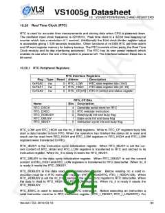
10.20.1 RTC Peripheral Registers
RTC Interface Registers
Reg Type Reset Abbrev
Description
0xFEA0
0xFEA1
r/w
r/w
0
0
RTC_LOW
RTC_HIGH
RTC data register bits [15:0]
RTC data register bits [31:16]
0xFEA2
r/w
0
RTC_CF[4:0] RTC if control and status register
RTC_CF Bits
Name
Bits Description
RTC_GSCK
RTC_EXEC
RTC_RDBUSY
RTC_DBUSY
RTC_IBUSY
4
3
2
1
0
Generate serial clock for RTC
RTC execute instruction
Read cycle init and busy flag
Data cycle init and busy flag
Instruction cycle init and busy flag
RTC_LOW and RTC_HIGH are the rtc_if data registers. Write to RTC_CF registers busy bits
start a data transfer to/from RTC. When the operation has finished the status bit is reset and
result can be read from RTC_HIGH and RTC_LOW registers or RTC_HIGH and RTC_LOW
registers were transferred to RTC.
RTC_IBUSY is the instruction cycle initialization register. When RTC_IBUSY is set the cur-
rent content of RTC_HIGH and RTC_LOW registers is transferred to RTC and latched to its
instruction register. When rtc_if is ready it resets the RTC_IBUSY.
RTC_DBUSY is the data cycle initialization register. When RTC_DBUSY is set the current
content of RTC_HIGH and RTC_LOW registers is transferred to RTC data buffer. When rtc_if
is ready it resets the RTC_DBUSY.
RTC_RDBUSY is the data read cycle initialization register. Before reading rtc a valid in-
struction must be in RTC instruction register (RTC_I_READRTC, RTC_I_RDDIV128). When
RTC_RDBUSY is set the rtc_if first samples the selected rtc register to RTC data buffer. When
the data is read to RTC_HIGH and RTC_LOW registers. When rtc_if is ready it resets the
RTC_RDBUSY.
RTC_EXEC is used to execute current RTC instruction. Before executing an instruction a
valid instruction must be in RTC instruction register (RTC_I_RESET, RTC_I_LOADRTC). For
Version: 0.2, 2012-03-16
94

 ETC [ ETC ]