VS1005g Datasheet
10 VS1005 PERIPHERALS AND REGISTERS
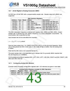
10.7 24-bit Digital to Analog Converter (DAC)
Vs1005 has a 24-bit DAC with a programmable sample rate. Sample rates up to 96kHz are
supported.
DAC Interface Registers
Address Type Reset Abbrev
Description
0xFC34
0xFC35
0xFC36
0xFC37
0xFC38
0xFC39
r/w
r/w
r/w
r/w
r/w
r/w
0
0
0
0
0
0
DAC_SRCL
DAC sample rate, bits 15-0
DAC sample rate, bits 19-16
DAC left sample, bits 7-0
DAC left sample, bits 23-8
DAC_SRCH[3:0]
DAC_LEFT_LSB[15:8]
DAC_LEFT
DAC_RIGHT_LSB[15:8] DAC right sample, bits 7-0
DAC_RIGHT DAC right sample, bits 23-8
The DAC interpolator frequency is defined with registers DAC_SRCH and DAC_SRCL. Output
sample rate is derived from the rollover frequency of a 20-bit interpolator accumulator. Its
accumulation rate is specified by ifreq.
Input sample rate can be calculated from equation:
fs = (fclk/227) ∗ ifreq where
Ifreq can have values from 1 to 1048575 (0xFFFFF) and fclk is the xtal clock frequency. Value
zero of ifreq places the DAC in idle mode. In idle mode all logic is halted. Also the analog clock
is halted.
Note that the DAC clock is not controlled by the PLL.
The exact sample rate is xtal dependent and a sample rate of e.g exactly 48kHz requires that
the xtal frequency is 12.288MHz.
24-bit samples are written to registers DAC_LEFT, DAC_LEFT_LSB, DAC_RIGHT and DAC_RIGHT_LSB
after each DAC interrupt.
10.7.1 Configuring Analog DAC Modules
Example values of analog configuration registers with 1.6V reference are given in next table.
Analog Control Register example for DAC Operation
Address
Register Value
Description
0xFECB ANA_CF1 0x0048 DAC and output driver power down
0xFED2 ANA_CF2 0x0018 Reference voltage select and reference power down
Version: 0.2, 2012-03-16
43

 ETC [ ETC ]