VS1005g Datasheet
10 VS1005 PERIPHERALS AND REGISTERS
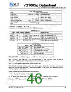
SRC Characteristics
Value Description
Item
Xtal Clock
11.0MHz - 13.0MHz Clock frequency
24 Input data width
DAC bit width
SRC bit widht
DAC sample rate 1
Output sample rate 1
Filter delay 2
Gain
24 Output data width
0Hz - 96kHz Input sample rate
0.97FSin - 192kHz Output sample rate
19 input samples
0.78
1
2
Assuming 12.288MHz XTAL clock.
In start-up the SRC output is valid after 19 DAC interrupts.
SRC Registers
Reg Type Reset Abbrev
Description
0xFEC6
0xFEC7
0xFED8
0xFED9
0xFEDA
r/w
r/w
r/w
r/w
r/w
0
0
0
0
0
SRC_CF
SRC_LEFT_LSB[15:12]
SRC_LEFT
SRC_RIGHT_LSB[15:12] SRC right sample bits [7:0]
SRC_RIGHT SRC right sample bits [23:8]
SRC sampler configuration register
SRC left sample bits [7:0]
SRC left sample bits [23:8]
SRC_CF Bits
Name Bits Description
SRC_CF_ORUN
SRC_CF_RFULL
SRC_CF_LFULL
SRC_CF_ENA
15
14
13
12
SRC overrun flag
Right data register full flag
Left data register full flag
Enable for sample rate convertter
SRC_CF_FS 11:0 SRC sample rate
SRC_CF_ORUN is set if data register was full when data registers were modified.
SRC_CF_RFULL and SRC_CF_LFULL status registers for new samples. Flags are set as
SRC_LEFT and SRC_RIGHT are modified and reset as they are read.
SRC_CF_ENA enables sample rate converter when set.
SRC_CF_FS is used to set src sample rate. This register defines the interval in clock cycles
when the samples are generated. When new samples are stored to data registers also an
interrupt request is generated.
Output sample rate can be calculated from equation:
fs = Fclk/(2 ∗ (src_cf_fs + 1)) where
src_cf_fs can have values from 0 to 4095 (0xFFF) and Fclk is the xtal clock frequency.
E.g. value 0x7FF gives sample rate of 12.288MHz / (2*(0x7FF+1)) = 3.0 kHz.
Version: 0.2, 2012-03-16
46

 ETC [ ETC ]