Ver 1.3
PRELIMINARY
EAGLE
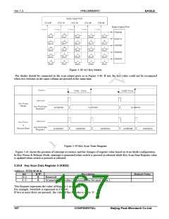
Figure 3-38 5x5 Key Matrix
The diodes should be connected to the scan output ports as in Figure 3-40. If not, the key value could not be recognized
when two switches in the same column are pressed at the same time.
Figure 3-39 Key Scan Time Diagram
Figure 3-41 shows the position of interrupt occurance and the changes of register value based on Scan Mode configuration.
In Key Presss & Release Mode, interrupt is generated when switch is pressed or released while Key Scan Data Register value
is updated when switch is pressed or released.
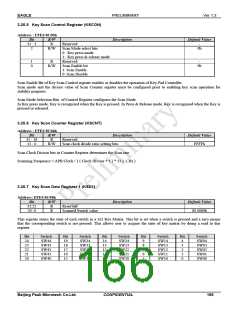
3.20.8 Key Scan Data Register 2 (KSD2)
Address: FFE0 8C0Ch
Bit
31:5
4: 0
R/W
R
R
Description
Default Value
Reserved
Scanned Switch value ( Represented as Decimal Value )
-
This Register represents the value of Register 1 in decimal.
For example, Switch04 is expressed as 4’b0101
If two or more Keys are pressed, the value of this Register is set to ‘0’.
167
CONFIDENTIAL
Beijing Peak Microtech Co.Ltd.

 ETC [ ETC ]