EAGLE
PRELIMINARY
Ver 1.3
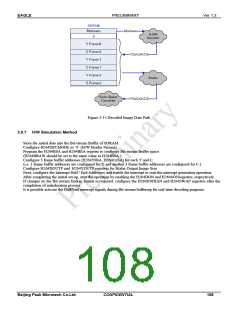
Figure 3-15 Decoded Image Data Path
3.9.7 H/W Simulation Method
Store the initial data into the Bit-stream Buffer of SDRAM.
Configure H264DECMODE as ‘0’ (H/W Header Parsing)
Program the H264BSA and H264BEA register to configure Bit-stream Buffer space.
(H264BRAW should be set to the same value as H264BSA.)
Configure 3 frame buffer addresses (H264YnSA, H264CnSA) for each Y and C.
(i.e. 3 frame buffer addresses are configured for Y and another 3 frame buffer addresses are configured for C.)
Configure H264XOUTP and H264YOUTP registers for Scalar Output Image Size.
Next, configure the Interrupt Half / End Addresses and enable the interrupt to start the interrupt generation operation.
After completing the initial set-up, start the operation by enabling the H264DON and H264SONregisters, respectively.
If changes on the Bit-stream Endian format is required, configure the H264ENDIAN and H264SWAP registers after the
completion of initialization process.
It is possible activate the Half/End interrupt signals during Bit-stream buffering for real-time decoding purposes.
Beijing Peak Microtech Co.Ltd.
CONFIDENTIAL
108

 ETC [ ETC ]