Ver 1.3
PRELIMINARY
EAGLE
0 : Disable
1 : Enable
Interrupt Selection register allows user to select either H264_IRQ0 or H264_IRQ1 as the decoder interrupt signals.
H264_IRQ0 is connected to Interrupt Vector 20, and H264_IRQ1 is connected to Interrupt Vector 30.
After initialization, Interrupt Enable register should be set to Enable.
3.9.5.2 Interrupt Flag Register (H264FLAG)
This register provides interrupt flag indicator for H.264 Decoder.
Address: FFE0 1CA4h
Bit
31 : 2
1
R/W
R
R
Description
Default Value
Reserved
Half Interrupt Flag
End Interrupt Flag
-
0b
0b
0
R
Half/End Interrupt flags are set to ‘1’, when the Decoder will generate the related interrupts by referring to the
Interrupt Half/End Address value. This register is cleared to ‘0’ by disabling the interrupt or by doing a read operation
to this register..
3.9.5.3 Interrupt Half Address Register (H264IHA)
This register sets the Interrupt Half Address of the Decoder.
Address: FFE0 1CA8h
Bit
R/W
Description
Default Value
31 : 0
R/W
Interrupt Half Address
0h
3.9.5.4 Interrupt End Address Register (H264IEA)
This register sets the Interrupt End Address of the Decoder.
Address: FFE0 1CACh
Bit
R/W
Description
Default Value
31 : 0
R/W
Interrupt Half Address
0h
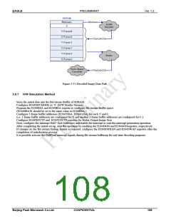
3.9.6 Decoded Image Data Path
Figure 3-15 describes the fundamentals of bit-stream decoding and shows the data path of decoded images using H.264
Decoder and Scalar. Bit-stream is read from the initial Start Address of Bit-stream Buffer, decoded, and stored into 3 Frame
Buffers as YCbCr (4:2:0) format in Macro Block unit. At the same time, H.264 Decoder switches the frame buffer bank and
informs Scalar regarding the readable frame.
Scaler reads the decoded image, scales the Image Size up and down based on the size configuration before transferring it
to the Color Space Converter as YCbCr (4:2:2) format in the unit of line.
The frame buffer size can be computed from the current decoding image size. The Y Buffer Size corresponds to one half
of the Image Size of C Buffer Size. For example, when H264F0MXS and H264F0MYS registers are configured as 14h and
Fh, respectively, the decoded image size is 320x240 (QVGA). Consequently, Y Buffer Size is ‘320 x 240 = 0x1_2C00’ and
C Buffer Size is ‘320 x 240 / 2 = 0x9600’.
107
CONFIDENTIAL
Beijing Peak Microtech Co.Ltd.

 ETC [ ETC ]