AND8242/D
Table 1. Features of Power Supply Using NCP1271
Operation Mode
Features
Topology
CCM/DCM Flyback
•
•
•
•
•
Fixed-frequency current-mode control with inherent primary current limitation.
Frequency jittering to soften the EMI signature.
Built-in soft-start.
Output short-circuit fault detection independent of the auxiliary winding.
Integrated high voltage startup that minimizes standby power loss.
Standby Condition
Fault Condition
Soft-Skip Operation
•
•
•
Adjustable skip level for optimal standby power consumption.
Proprietary Soft-Skip to reduce the risk of low-frequency audible noise.
Soft-Skip operation is automatically disabled if an abrupt transient load is applied
from standby operation. This improves the output response to a transient load.
Double Hiccup
Restart
•
Double Hiccup operation minimizes the power dissipation in a fault mode and
allows the application to auto-recover when the fault is removed.
Latch Protection
Activated
Latch Off
•
•
An internal latch makes it easy to add overtemperature protection (OTP) or
overvoltage protection (OVP) to any applications.
Latch is reset by unplugging the AC input and allowing V to drop below 4 V (typ).
CC
The Demo Board Specification
Based on the results from the NCP1271 design
spreadsheet, the final values for this adapter's key flyback
parameters were calculated to be:
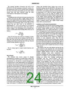
Np:Ns = 5:1
Input
85 to 265 Vac, 50 Hz
19 Vdc, 3.0 A, Isolated
Output
Features
•
•
•
•
•
< 100 mW Input Power at 230 Vac
Excellent Light Load Performance
No Audible Noise
Lp = 180 mH
R
= 0.3 Ohms
CS
Ipeak(full load) = 3.5 A
Switch Rating = 6 A, 800 V
Diode Rating = 3 A, 100 V
Rsnubber = 100 kW
> 85% Full Load Efficiency
Short Circuit Protection Activates at < 100W
for Any Input Voltage
A Discontinuous Conduction Mode (DCM) flyback was
selected for this application. DCM gives very good stability,
small inductor size (lower leakage inductance), and good
transient response.
Csnubber = 10 nF
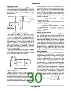
Setting the Short Circuit Protection Level
The current sense resistor (R or R8), provides two
CS
functions. First it senses the primary current for current- mode
PWM operation. Secondly, it provides the maximum primary
current limitation according to equation 1:
Flyback Calculations
Several resources are available at www.onsemi.com to
calculate the necessary component values for a flyback
supply. In particular, an Excel based design spreadsheet can
be found at:
1ꢀV
I
+
(eq. 1)
p(max)
R
CS
The short circuit protection activates when the I
www.onsemi.com/collateral/NCP1271SHEET.xls
Additionally, most of the other NCP12xx application
notes also apply to the NCP1271. For detailed information
on designing a flyback power supply, please visit
AND8076/D. Other app notes which may also aid in the
design include:
p(max)
current is reached for more than 130 ms (typ). This also
corresponds to V being greater than or equal to 3 V for
130 ms. Therefore, R must be set large enough to ensure
FB
CS
that the required peak current can always be delivered, but
small enough to meet the short circuit protection
requirements. A DCM flyback converter has the following
relationship:
AND8069/D
AND8205/D
AND8023/D
AND8032/D
AND8076/D
Tips and Tricks to Build Efficient Circuits
With the NCP1200
2
P
+ 1ń2 L I F
h
SW
(eq. 2)
How to Choose a Switching Controller for
Design
out
p
p
Therefore, for an assumed efficiency of 80%, a peak
current of 4 A should trigger the short circuit protection
circuitry at 80 W. This corresponds to an R value of
Implementing the NCP1200 in Low-Cost
AC/DC Converters
CS
0.25 W. This change in R may also require that the snubber
CS
Conducted EMI Filter Design for the
NCP1200
and transformer be re-calculated to handle this level of peak
current during the short circuit fault time. A few iterations
of the Excel based NCP1271 design spreadsheet should
produce a good starting point for the application's design.
A 70 W Low Standby Power Supply with the
NCP12xx Series
http://onsemi.com
2

 ETC [ ETC ]