AND8242/D
Maximum Duty Cycle and Ramp Compensation
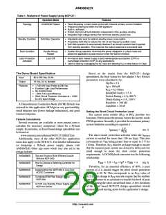
If the ramp resistor is set too high, the maximum duty
cycle will be reduced. But as a long as R is below 10 kW,
NTC
resistor
ramp
this will not be a problem. A typical graph of the maximum
duty cycle verses R is shown in Figure 7. However, it is
ramp
not recommended to try to reduce the maximum duty cycle
by the R value because this relationship is not
guaranteed by the production tests of the device.
R
limit
ramp
1
8
2
3
4
90
6
5
80
70
60
50
40
30
20
10
0
NCP1271
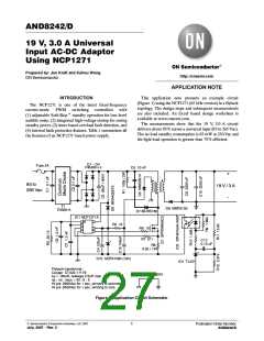
Figure 9. Overtemperature Protection Latch with a
NTC Thermistor
0
5
10
15
20
25
30
35
40
45 50
R
limit
R
, RESISTOR (kW)
RAMP
OVP
1
2
3
4
8
Figure 7. Maximum Duty Cycle Characteristics
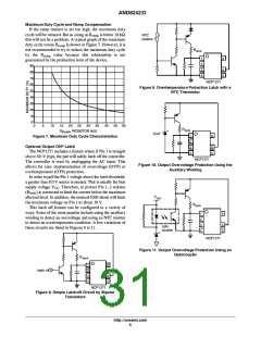
Optional Output OVP Latch
6
5
The NCP1271 includes a feature where if Pin 1 is brought
above 8.0 V (typ), the part will safely latch off the controller.
The controller is reset by unplugging the AC input. This
allows for easy implementation of overvoltage (OVP) or
overtemperature (OTP) protection.
NCP1271
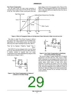
Figure 10. Output Overvoltage Protection Using the
Auxiliary Winding
In order to pull the Pin 1 voltage above the latch threshold,
a greater than 8.0 V source is needed. That is usually the bias
supply voltage V . Therefore, to protect Pin 1, a resistor
CC
(R ) is connected to limit the current below the maximum
limit
V
allowed level. In addition, the internal ESD diode will limit
the maximum voltage on Pin 1 to about 10 V.
out
R
limit
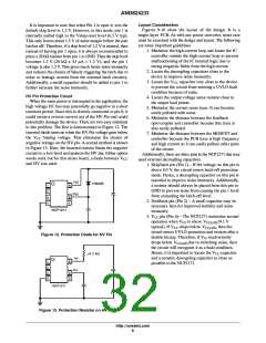
This latch off feature can be configured in a variety of
ways. Some of the most popular include using the auxiliary
winding to detect an overvoltage and using an NTC resistor
to detect an overtemperature condition. A few variations of
these circuits are listed in Figures 8 to 11.
1
2
3
4
8
6
5
opto
coupler
NCP1271
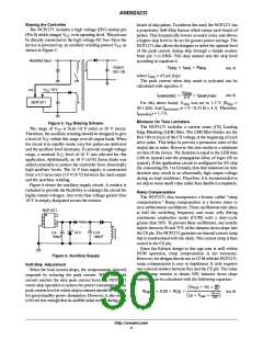
Figure 11. Output Overvoltage Protection Using an
Optocoupler
R
limit
1
2
3
4
8
latch off
6
5
NCP1271
Figure 8. Simple Latchoff Circuit by Bipolar
Transistors
http://onsemi.com
5

 ETC [ ETC ]