1-2-1 2-Phase Stepper Motor Unipolar Driver ICs
SLA7075MR, MPR/7076MR, MPR/7077MR, MPR/7078MR, MPR 2-Phase/4 W1-2 Phase Excitation Support, Built-in Sequencer
■Features
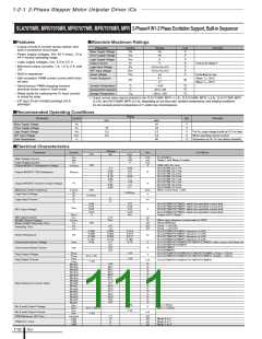
■Absolute Maximum Ratings
• Lineup of built-in current sense resistor and
built-in protection circuit-type
Parameter
Symbol
Ratings
Unit
V
Remarks
Motor Supply Voltage
Driver Supply Voltage
Logic Supply Voltage
Output Current
V
M
46
• Power supply voltages, VBB: 46 V (max), 10 to
44 V normal operating range
V
BB
46
V
VDD
6
*1
V
• Logic supply voltages, VDD: 3.0 to 5.5 V
Io
A
Vref=0.4V, Mode F
• Maximum output currents: 1 A, 1.5 A, 2 A, and
3 A
Logic Input Voltage
REF Input Voltage
Sense Voltage
V
IN
REF
RS
–0.3 to VDD+0.3
–0.3 to VDD+0.3
±2
V
V
V
• Built-in sequencer
V
V
Excluding tw<1µs
Power Dissipation
4.7
When T
a
= 25°C
= 25°C
• Self-excitation PWM current control with fixed
off-time
PD
W
17
When T
c
Junction Temperature
Operating Ambient Temperature
Storage Temperature
T
j
+150
°C
°C
°C
• Synchronous PWM chopping function
prevents motor noise in Hold mode
Ta
–20 to +85
–30 to +150
Tstg
• Sleep mode for reducing the IC input current
in stand-by state
*1: Output current value may be limited for the SLA7075MR, MPR (1.0 A), SLA7076MR, MPR (1.5 A), SLA7077MR, MPR
(2.0 A), and SA7078MR, MPR (3.0 A), depending on the duty ratio, ambient temperature, and heating conditions.
Do not exceed junction temperature of Tj under any circumstances.
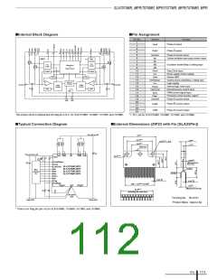
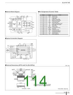
• ZIP type 23-pin molded package (SLA
package)
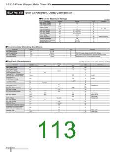
■Recommended Operating Conditions
Rating
Parameter
Symbol
Unit
Remarks
min.
max.
44
Motor Supply Voltage
VM
VS
V
V
Driver Supply Voltage
Logic Supply Voltage
REF Input Voltage
Case Temperature
10
3.0
0.0
44
VDD
VREF
TC
5.5
0.4
90
V
The VCC surge voltage should be 0.5 V or lower
When operating current control
V
°C
Temperature at Pin-12 Lead (without heatsink)
■Electrical Characteristics
Parameter
Ratings
typ.
Symbol
Unit
Conditions
min.
100
max.
15
100
5
mA
µA
mA
V
In operation
Sleep 1 and Sleep 2 modes
IBB
Main Supply Current
I
BBS
Logic Supply Current
Output MOSFET Breakdown Voltage
Icc
(BR)DSS
VBB=44V, ID=1mA
SLA7075M, ID=1.0A
SLA7076M, ID=1.5A
SLA7077M, ID=2.0A
SLA7078M, ID=3.0A
SLA7075M, ID=1.0A
SLA7076M, ID=1.5A
SLA7077M, ID=2.0A
SLA7078M, ID=3.0A
When Clock Duty = 50%
V
0.7
0.45
0.25
0.18
0.85
1.0
0.85
0.6
0.4
0.24
1.1
1.25
1.2
Ω
Output MOSFET ON Resistance
RDS(ON)
V
F
V
Output MOSFET Diode Forward Voltage
0.95
0.95
2.1
250
kHz
V
Maximum Clock Frequency
Logic Input Voltage
Fclock
0.25VDD
V
IL
IH
IL
IH
0.75VDD
V
I
I
1
1
µA
Logic Input Current
0.04
0.04
0.04
0.04
2
0.3
0.45
0.4
0.45
VDD
SLA7075MR/7075MPR, within the specified current limit
SLA7077MR/7076MPR, within the specified current limit
SLA7077MR/7077MPR, within the specified current limit
SLA7078MR/7078MPR, within the specified current limit
Output (OFF) Sleep 1
V
REF
V
REF Input Voltage
V
I
REFS
REF
10
REF
µA
V
µS
µS
µS
REF Input Current
SENSE Sense Voltage
Sleep-Enable Recovery Time
V
When step reference current ratio is 100%
Sleep1&Sleep2
Clock → Out ON
V
SENSE
SE
100
T
2.0
1.5
tcon
Switching Time
Clock → Out OFF
tcoff
0.296
0.296
0.199
0.150
0.65
0.305
0.305
0.205
0.155
0.7
2.3
3.5
4.6
0.314
0.314
0.211
0.160
0.75
SLA7075MR/7075MPR, tolerance of 3%
SLA7076MR/7076MPR, tolerance of 3%
SLA7077MR/7077MPR, tolerance of 3%
SLA7078MR/7078MPR, tolerance of 3%
SLA7075MPR/7076MPR/7077MPR/7078MPR, when motor coil shorts out
SLA7075MPR/7076MPR
Ω
Sense Resistance
R
S
V
A
Overcurrent Sense Voltage
Overcurrent Sense Current
V
ocp
SLA7077MPR
SLA7078MPR
I
ocp
1.25
1.25
SLA70750MPR/7076MPR/7077MPR/7078MPR, IFlagL=1.25mA
SLA7075MPR/7076MPR/7077MPR/7078MPR, IFlagH=-1.25mA
V
FlagL
Flag Output Voltage
Flag Output Current
V
V
DD–1.25
V
FlagH
FlagL
FlagH
I
I
mA
SLA7075MPR/7076MPR/7077MPR/7078MPR
–1.25
100
98.1
95.7
92.4
88.2
83.1
77.3
70.7
63.4
55.5
47.1
38.2
29.0
19.5
9.8
%
%
%
%
%
%
%
%
%
%
%
%
%
%
%
ModeF
ModeE
ModeD
ModeC
ModeB
ModeA
Mode9
Mode8
Mode7
Mode6
Mode5
Mode4
Mode3
Mode2
Mode1
Step Reference Current Ratio
1.25
1.25
I
MOL=1.25mA
V
V
I
I
MOL
MOH
MOL
MOH
V
Mo (Load) Output Voltage
V
DD–1.25
I
MOH=–1.25mA
mA
Mo (Load) Output Current
PWM Minimum ON Time
–1.25
1.7
12
9
µS
µS
µS
µS
ton(min)
toff1
toff2
Mode 8 to F
Mode 4 to 7
Mode 1 to 3
PWM OFF Time
7
toff3
ICs
110

 ETC [ ETC ]