DM9101
10/100Mbps Ethernet Physical Layer Single Chip Transceiver
Pin Description (continued)
Pin No.
LQFP QFP
Device Configuration/Control/Status Interface (continued)
Pin Name
I/O
Description
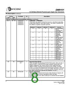
OPMODE0 - OPMODE3:
88-91
90 - 93
OPMODE0
OPMODE1
OPMODE2
OPMODE3
I
These pins are used to control the forced or advertised operating
mode of the DM9101 (see table below). The value is latched into
the DM9101 registers at power-up/reset.
OPMODE3
OPMODE2
OPMODE1
OPMODE0
Function
0
0
0
0
Auto-neg enable
with all
capabilities with
Flow Control
Auto-neg enable
without all
0
0
0
1
capabilities
without Flow
Control
0
0
0
0
1
1
0
1
Auto-neg 100TX
FDX with Flow
Control only
Auto-neg 100TX
FDX/HDX
without Flow
Control
0
0
1
1
0
0
0
1
Auto-neg 10TP
FDX with Flow
Control only
Auto-neg 10TX
FDX/HDX
without Flow
Control
0
0
1
1
1
1
0
0
1
1
0
0
0
1
0
1
Manual select
100TX FDX
Manual select
100TX HDX
Manual select
10TX FDX
Manual select
10TX HDX
Repeater/Node Mode:
92
93
94
95
RTPR/NOD
E#
I
I
When set high, this bit selects REPEATER mode; when set low, it
selects NODE. In REPEATER mode or NODE mode with Full
Duplex configured, the Carrier Sense (CRS) output from the
DM9101 will be asserted only during receive activity. In NODE
mode or a mode not configured for Full Duplex operation, CRS will
be asserted during receive or transmit activity. At power-up/reset,
the value on this pin is latched into Register 16, bit 11.
Bypass Alignment:
BPALIGN
Allows 100Mbps transmit and receive data streams to bypass all
of the transmit and receive operations when set high.
At power-up/reset, the value on this pin is latched into bit Register
16 ,bit 13.
8
Final
Version: DM9101-DS-F03
July 22, 1999

 ETC [ ETC ]