DM9101
10/100Mbps Ethernet Physical Layer Single Chip Transceiver
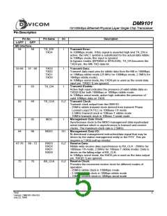
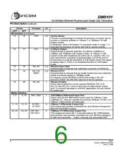
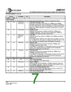
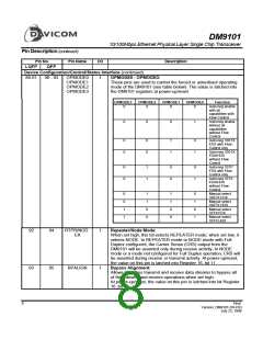
Pin Description (continued)
Pin No.
LQFP QFP
Device Configuration/Control/Status Interface (continued)
Pin Name
I/O
Description
Bypass 4B5B Encoder/Decoder:
94
95
96
96
97
98
BP4B5B
I
I
I
Allows 100Mbps transmit and receive data streams to bypass the
4B to 5B encoder and 5B to 4B decoder circuits when set high
At power-up/reset, the value on this pin is latched into Register
16, bit 15.
Bypass Scrambler/Descrambler:
BPSCR
Allows 100Mbps transmit and receive data streams to bypass the
scrambler and descrambler circuits when set high.
At power-up/reset, the value on this pin is latched into Register
16, bit 14.
Serial/Nibble Select:
10BTSER
10Mbps Serial Operation:
When set high, this input selects a serial data transfer mode.
Manchester encoded transmit and receive data is exchanged
serially with a 10MHz clock rate on the least significant bits of the
nibble-wide MII data buses, pin TXD[0] and RXD[0] respectively.
This mode is intended for use with the DM9101 connected to a
device (MAC or Repeater) that has a 10Mbps serial interface.
Serial operation is not supported in 100Mbps mode. For
100Mbps, this input is ignored.
10 and 100Mbps Nibble Operation:
When set low, this input selects the MII compliant nibble data
transfer mode. Transmit and receive data is exchanged in nibbles
on the TXD[3:0] and RXD[3:0] pins respectively.
At power-up/reset, the value on this pin is latched into Register
18, bit 10.
Clock Interface
Crystal or Oscillator Input:
27
29
OSCI/X1
I
This pin should be connected to a 25MHz (±50 ppm) crystal if
OSC/XTL#=0 or a 25MHz (±50ppm) external TTL oscillator input,
if OSC/XTLB=1.
Crystal Oscillator Output:
28
30
30
32
X2
O
I
An external 25MHz (±50 ppm) crystal should be connected to this
pin if OSC/XTL#=0, or left unconnected if OSC/XTL#=1.
Crystal or Oscillator Selector Pin:
OSC/XTL#
OSC/XTL#=0: An external 25MHz (±50ppm) crystal should be
connected to X1 and X2 pins.
OSC/XTL#=1: An external 25MHz (±50ppm) oscillator should be
connected to X1 and X2 should be left
unconnected.
25MHz Clock Output:. This clock is derived directly from the
crystal circuit.
46
48
CLK25M
O,Z
Final
9
Version: DM9101-DS-F03
July 22, 1999

 ETC [ ETC ]